
Method and long-stator linear motor for transferring a transport unit at a transfer position
a technology of longstator and transport unit, which is applied in the direction of transportation and packaging, propulsion systems, and association with control/drive circuits. it can solve the problems of increasing the effort needed to implement a transport device, inability to individually transport individual transport units, and inability to transfer individual transport units
- Summary
- Abstract
- Description
- Claims
- Application Information
AI Technical Summary
Benefits of technology
Problems solved by technology
Method used
Image

Examples
first embodiment
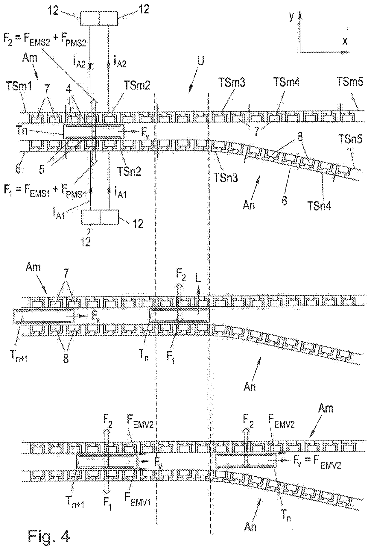
[0019]FIG. 4 shows a method according to the invention for transferring a transport unit at a transfer position; and
second embodiment
[0020]FIG. 5 shows a method according to the invention for transferring a transport unit at a transfer position.
DETAILED DESCRIPTION OF THE EMBODIMENTS
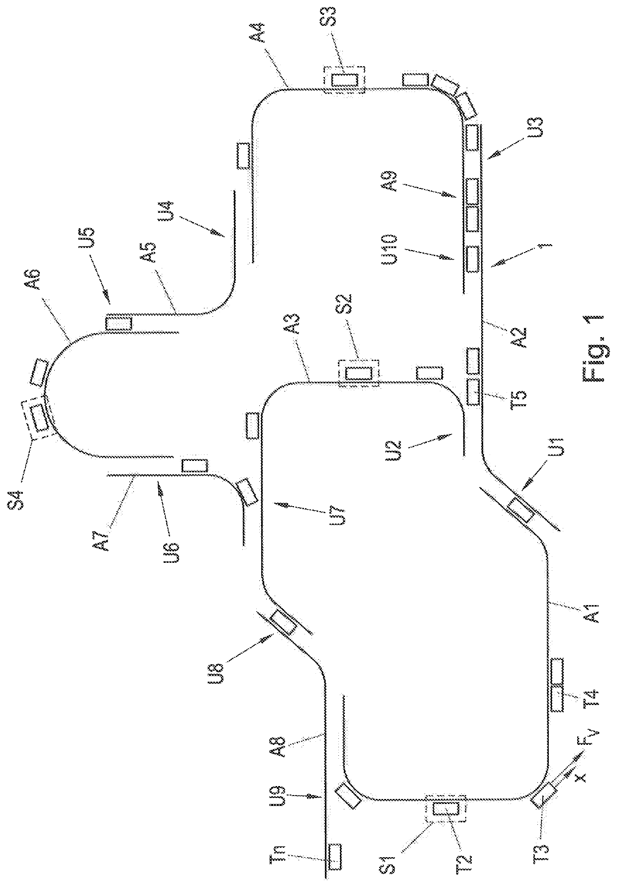
[0021]FIG. 1 shows an example of a transport device 1 in the form of a long-stator linear motor. The transport device 1 consists of a number of transport sections A1 . . . A9, which are combined to form a transport device 1. This modular structure enables a very flexible design of the transport device 1, but also requires a plurality of transfer positions U1 . . . U9, at which the transport units T1 . . . Tn moved on the transport device 1 are transferred from one transport sections A1 . . . A9 to another (for reasons of clarity, not all transport units are marked with a reference sign in FIG. 1). n is an index that stands for the existing number of transport units.
[0022]The transport device 1 is designed as a long-stator linear motor in which the transport sections A1 . . . A9 each form a part of a long-stator of a long-stator linear...
PUM
 Abstract
Description
Claims
Application Information