Linear LED driver and control method thereof

a technology of led driver and led light, applied in the direction of electric variable regulation, process and machine control, instruments, etc., can solve the problems of bleeder circuits that need extra high-voltage components or pins, led flickering, and high cost, so as to prevent bleeder current, prevent led flickering, and prevent led flickering

Inactive Publication Date: 2016-09-20
RICHTEK TECH
View PDF11 Cites 1 Cited by
  • Summary
  • Abstract
  • Description
  • Claims
  • Application Information

AI Technical Summary

Benefits of technology

[0007]An objective of the present invention is to provide a linear LED driver that prevents the LED from flickering and a method thereof.
[0008]Another objective of the present invention is to provide a linear LED driver that avoids generating a bleeder current during the LED turned on and a method thereof.
[0010]According to the present invention, a linear LED driver comprises at least one first transistor, a voltage supply terminal for providing a driving voltage to drive LEDs, a voltage regulator, and a bleeder circuit. Each of the at least one first transistor has an input terminal coupled to the LEDs and lights up or turns off the LEDs. The voltage regulator is coupled to the voltage supply terminal and is converting the driving voltage into a power voltage used by the LED driver. The bleeder circuit detects a voltage of the output terminal of each the at least one first transistor and the power voltage. The bleeder circuit generates a bleeder current that flows through the voltage regulator when a voltage of the output terminal of each the at least one first transistor is lower than a first threshold and the power voltage is higher than a second threshold, thereby preventing the LEDs from flickering. Wherein, the voltage regulator is an original part built in the linear LED driver. Moreover, the voltage regulator also requires a high-voltage component to bear the driving voltage on the voltage supply terminal. Thus, the bleeder circuit that draws a current from the voltage supply terminal via the voltage regulator doesn't need extra high-voltage components or pins. Additionally, the bleeder circuit detects the voltage of the output terminal of each the at least one first transistor, so that whether the LEDs are lighted can be confirmed, and the bleeder current can be prevented from being generated during the LED turned on.
[0011]According to the present invention, a linear LED driver comprises at least one first transistor, a voltage supply terminal for providing a driving voltage to drive LEDs, and a bleeder circuit. Each of the at least one first transistor has an input terminal coupled to the LEDs and lights up or turns off the LEDs. The bleeder circuit detects a voltage of an output terminal of each the at least one first transistor and the power voltage. The bleeder circuit will generate a bleeder current to discharge the voltage supply terminal when the voltage of the output terminal of each the at least one first transistor is lower than a first threshold and the power voltage is higher than a second threshold, thereby preventing the LEDs from flickering. Wherein, the bleeder circuit detects the voltage of the output terminal of each the at least one first transistor. Thus, whether the LEDs are lighted can be confirmed. As a result, the bleeder current can be prevented from being generated during the LEDs turned on.
[0012]According to the present invention, a method for controlling the linear LED driver comprises the steps of: providing a power voltage used by the linear LED driver; and generating a bleeder current to discharge voltage supply terminal which is providing a driving voltage to drive LEDs when the voltage of the output terminal of each at least one first transistor is lower than a first threshold and the power voltage is higher than a second threshold, thereby the LEDs can be prevented from flickering. Wherein, each of the at least one first transistor has an input terminal coupled to the LEDs. The present invention detects the voltage of the output terminal of each the at least one first transistor to realize whether the LEDs are lighted. Preferably, the bleeder current can be prevented from being generated during the LEDs turned on.

Problems solved by technology

A LED driver of isolated type needs a transformer to isolate the primary side from the secondary side, and thus requires higher costs.
Such undesired variation may shortly turn on the LED which should have been turned off and easily cause the flickering on the LED.
However, the driving voltage VIN is a high voltage, so the existing bleeder circuits need extra high-voltage components or pins.
As a result, the related costs are higher.
Thus, the fixed threshold is difficult to be defined.
Referring to FIG. 2, when the fixed threshold is too high as shown by the waveform 36, the bleeder current Ibd will be generated when the LED is still lighted as shown by the waveform 40, which adversely results in a low efficiency.

Method used


Image

  • Linear LED driver and control method thereof
  • Linear LED driver and control method thereof
  • Linear LED driver and control method thereof

Examples


first embodiment

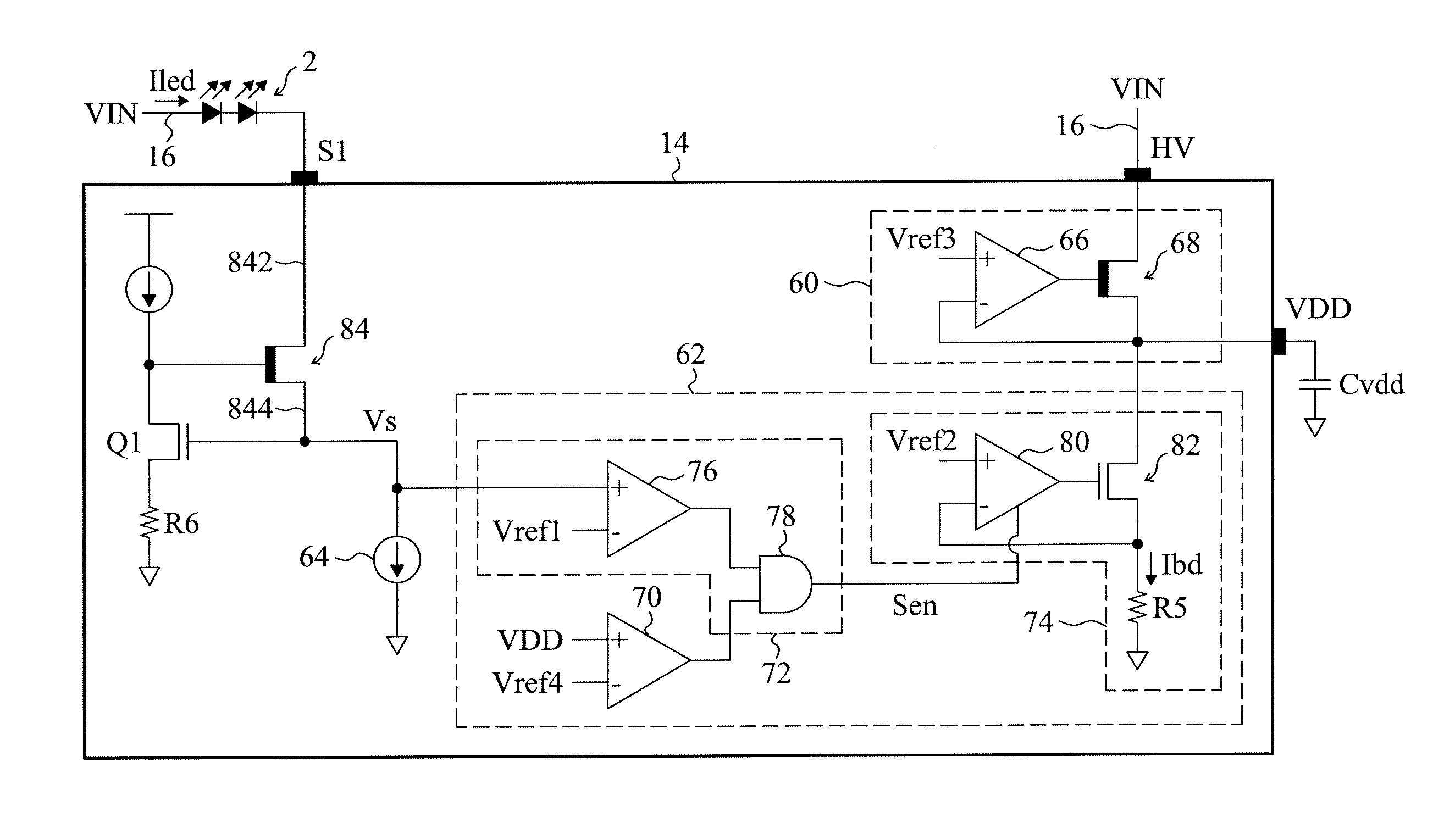
[0029]FIG. 6 shows the present invention. FIG. 6 only shows a control circuit in an IC 14. Other parts of the linear LED driver 10 can be referred to FIGS. 1 and 3. The IC 14 in FIG. 6 comprises a voltage regulator 60, a bleeder circuit 62, a current source 64 and a transistor 84. The transistor 84 includes an input terminal 842 coupled to an LED 2 via a pin S1. The switching of the transistor 84 controls the LED 2 to be lighted up or turned off. The transistor 84 adopts a high-voltage component such as the metal-oxide-semiconductor field effect transistor (MOSFET) or the insulated gate bipolar transistor (IGBT). The current source 64 is coupled to an output terminal 844 of the transistor 84 for regulating a current Iled that goes through the LED 2. The voltage regulator 60 is coupled to a voltage supply terminal 16 via a pin HV, thereby converting a driving voltage VIN into a power voltage VDD used by the linear LED driver 10. The voltage regulator 60 includes an operation amplifie...

third embodiment

[0034]FIG. 10 shows the present invention. Similar to that of FIG. 7, the circuit in FIG. 10 also comprises the transistors 84, 86, 88, and 90 for respectively controlling the LEDs 2, 4, 6, and 8, the voltage regulator 60 for converting the driving voltage VIN into the power voltage VDD, and the bleeder circuit 62 for providing the bleeder current. Differently, the detecting circuit 72 of the bleeder circuit 62 in FIG. 10 utilizes more than one comparators 102, 104, 106, and 108 to detect a voltage Vs1 of the output terminal 844 of the transistor 84, a voltage Vs2 of the output terminal 864 of the transistor 86, a voltage Vs3 of the output terminal 884 of the transistor 88, and a voltage Vs4 of the output terminal of the transistor 90, respectively. Moreover, the detecting circuit 72 in this embodiment also utilizes an OR gate 110 to handle the outputs of the comparators 102, 104, 106, and 108, thereby determining whether to enable the current source 74 to generate the bleeder curre...

fourth embodiment

[0035]FIG. 11 shows the present invention. The circuit of FIG. 11 is similar to that of FIG. 6. Differently, the bleeder circuit 62 in FIG. 11 is not coupled to the voltage supply terminal 16 via the voltage regulator 66 and the pin HV. The bleeder circuit 62 in this embodiment is directly coupled to the voltage supply terminal 16 via another pin BD. The bleeder circuit 62 directly bears the driving voltage VIN which is a high voltage, so the transistor 82 of the current source 74 in the bleeder circuit 62 has to adopt a high-voltage component. The operation of the circuit in FIG. 11 is also similar to that in FIG. 6. When the voltage Vs of the output terminal 844 of the transistor 84 is lower than the threshold Vref1, it is meaning that the LED 2 is turned off. At this time, the detecting circuit 72 generates an enable signal Sen to enable the current source 74 so as to generate the bleeder current Ibd to prevent the LED 2 from flickering. When the power voltage VDD is lower than t...


PUM


Abstract

A linear LED driver includes a voltage supply terminal providing a driving voltage, at least one first transistor, each of which has an input terminal coupled to a respective LED, and a bleeder circuit. When the voltage of the output terminal of each of the at least one first transistor is lower than a first threshold and a power voltage is higher than a second threshold, the bleeder circuit will generate a bleeder current to discharge the voltage supply terminal so as to prevent the LEDs from flickering. The bleeder circuit detects the voltage of the output terminal of each of the at least one first transistor. Therefore, whether the LEDs are lighted up can be confirmed so that the bleeder current can be provided at properly time point.

Description

CROSS-REFERENCE TO RELATED APPLICATIONS[0001]This application claims the priority benefit of Taiwan Application No. 104104844, filed Feb. 12, 2015, the contents of which in its entirety are herein incorporated by reference.FIELD OF THE INVENTION[0002]The present invention is related generally to a linear light emitting diode (LED) driver and control method and, more particularly, to a linear LED driver and a control method thereof that can prevents LEDs from flickering.BACKGROUND OF THE INVENTION[0003]LED drivers can be generally classified into isolated type and non-isolated type. A LED driver of isolated type needs a transformer to isolate the primary side from the secondary side, and thus requires higher costs. A LED driver of non-isolated type needs lower costs due to absence of the transformer, while flickering in triode alternating current (TRIAC) dimming applications.[0004]FIG. 1 shows a conventional linear LED driver 10 of non-isolated type, which includes a bridge rectifier...

Claims


Application Information

Patent Timeline
Patent Type & Authority Patents(United States)
IPC IPC(8): G05F1/00H05B33/08H05B44/00
CPCH05B33/0812H05B33/0845H05B45/10H05B45/48
Inventor JAO, TONG-CHENGLEE, YI-WEIPAN, JIUN-HUNGCHEN, ISAAC Y.
Owner RICHTEK TECH
Why Eureka
Try Eureka