
Liquid crystal panel and display device containing same

A liquid crystal panel and the same technology are applied in the fields of power saving, display devices, and high-quality liquid crystal panels, which can solve problems affecting image quality, increasing source driver power consumption, and affecting accuracy, so as to improve image quality and eliminate disadvantages Influence, the effect of ensuring correctness

Inactive Publication Date: 2010-01-27
KUSN INFOVISION OPTOELECTRONICS
View PDF0 Cites 35 Cited by
  • Summary
  • Abstract
  • Description
  • Claims
  • Application Information

AI Technical Summary

Problems solved by technology

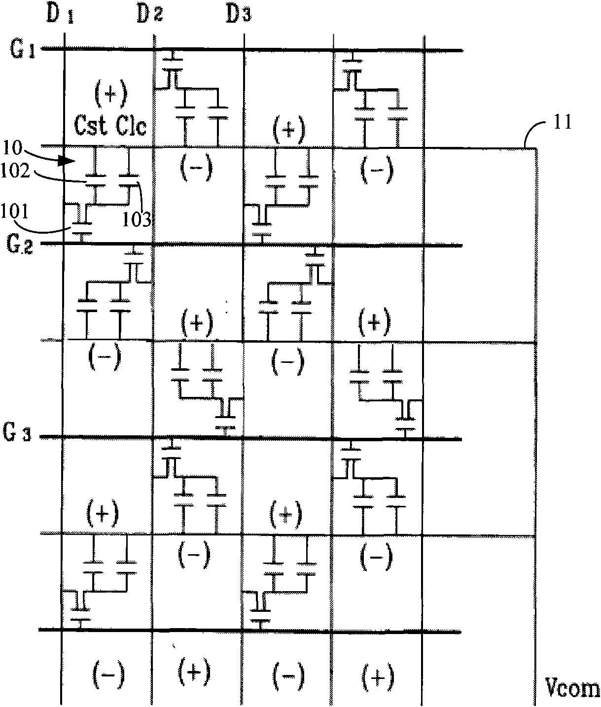
[0008] Due to the driving circuit of the LCD device of the prior art in-plane switching (IPS) liquid crystal display device (or fringe field switching (FFS) liquid crystal display device), a constant DC value (ie, a direct current voltage) is provided as a common voltage, and In different frames, positive and negative data voltages are alternately provided to the data lines. Since the polarity and magnitude of the liquid crystal voltage applied to both ends of the liquid crystal capacitor in the pixel unit depends on the polarity and magnitude of the data voltage and the magnitude of the common voltage, in order To stabilize the liquid crystal voltage to a desired value, a source driver with a large output voltage difference must be used to apply the voltage to the pixel unit 10, which will increase the power consumption of the source driver and increase the cost of using the liquid crystal panel
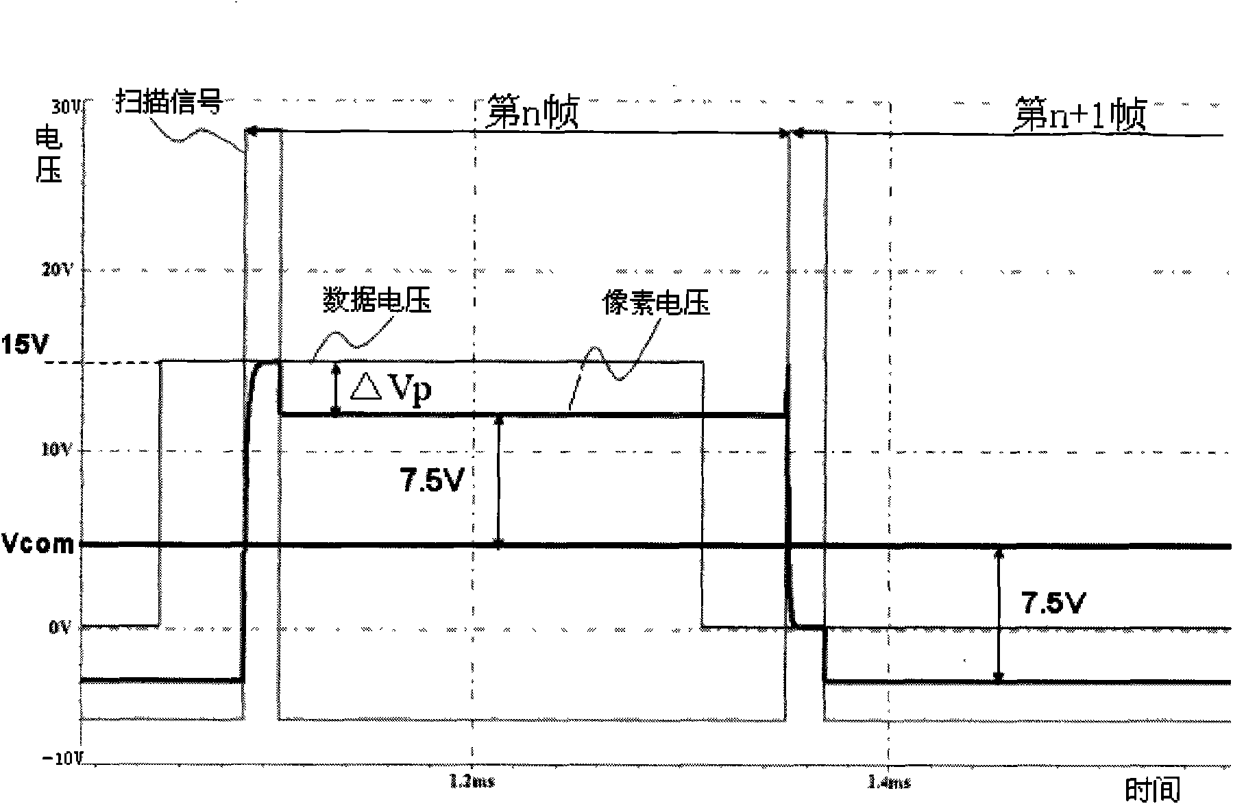
[0009] At the same time, it can also be seen that because the pixel voltage has a level-shifting voltage, that is, the feed-through voltage ΔVp, it will cause distortion of the liquid crystal voltage and affect the accuracy of the gray-scale display of the liquid crystal panel, resulting in display defects such as flickering and afterimages. , affecting image quality

Method used


Image

  • Liquid crystal panel and display device containing same
  • Liquid crystal panel and display device containing same
  • Liquid crystal panel and display device containing same

Examples


Embodiment Construction

[0022] In order to make the above objects, features and advantages of the present invention more comprehensible, the present invention will be further described in detail below in conjunction with the accompanying drawings and specific embodiments.

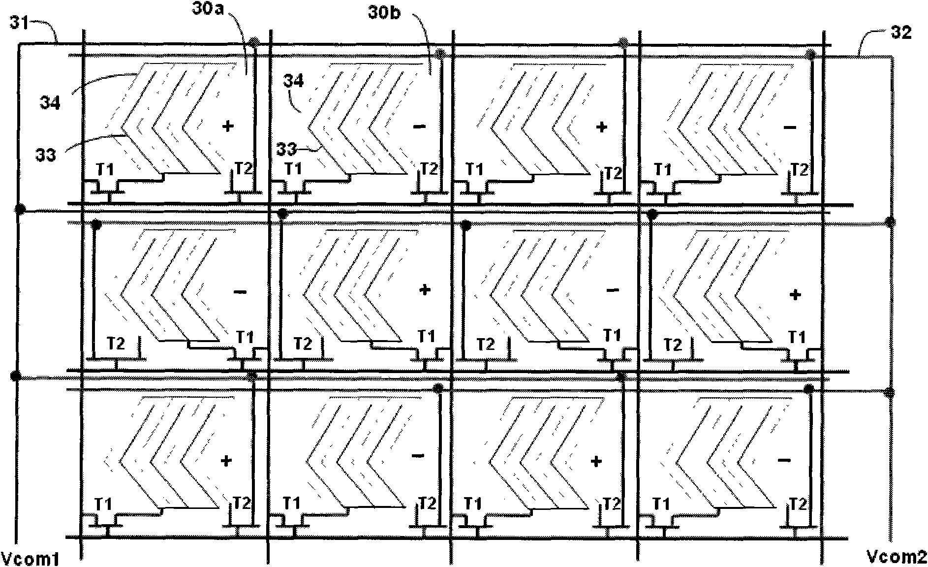
[0023] refer to image 3 , image 3 It is a layout plan view of the liquid crystal panel of the present invention. The coplanar switching liquid crystal panel of the present invention has a first pixel unit, a second pixel unit, a first common line and a second common line, and the common lines of the first pixel units in each row of pixel units are The electrodes are connected to the first common line through the second switch element, and the common electrode of the second pixel unit is connected to the second common line through the second switch element. The first common line and the second common line apply a first common voltage and a second common voltage respectively, and the first common voltage and the second common vol...


PUM


Abstract

The invention relates to a liquid crystal panel and a display device containing the same, wherein, the liquid crystal panel comprises a plurality of pixel units; each pixel unit comprises a gating line, a data line, a pixel electrode and a first switch element; the common electrode of a first pixel unit and a second pixel unit is connected to a first common line and a second common line respectively by a second switch element in the pixel units at the same line of the liquid crystal panel, wherein, the first common line is connected to a first common voltage, the second common line is connected to a second common voltage, the first common voltage and the second common voltage are AC voltage, and the voltage levels in the same frame are opposite; meanwhile, the first switch element and the second switch element are equivalently designed thin-film transistors. The liquid crystal panel of the invention can reduce the power consumption of a source driver and improve the quality of images.

Description

technical field [0001] The invention relates to a liquid crystal panel, in particular to a power saving, high-quality liquid crystal panel and a display device comprising the liquid crystal panel. Background technique [0002] With the expansion of the application range of the liquid crystal display device, the liquid crystal panel itself has also achieved better development. In order to realize wide viewing angles in liquid crystal display devices, various technologies have been developed, such as twisted nematic liquid crystal (TN) display with wide viewing film (wide viewing film), in-plane switching (IPS) liquid crystal display , fringe field switching (FFS) liquid crystal display and multi-domain vertical alignment (MVA) liquid crystal display, etc. At the same time, in order to improve the display quality of the liquid crystal display device, the existing liquid crystal display device generally adopts the dot inversion driving technology, but this requires a source dr...

Claims


Application Information

Patent Timeline
Patent Type & Authority Applications(China)
IPC IPC(8): G02F1/1362G02F1/1368G09G3/36
Inventor 钟德镇邱郁雯廖家德
Owner KUSN INFOVISION OPTOELECTRONICS
Learn More