Display panel and display device

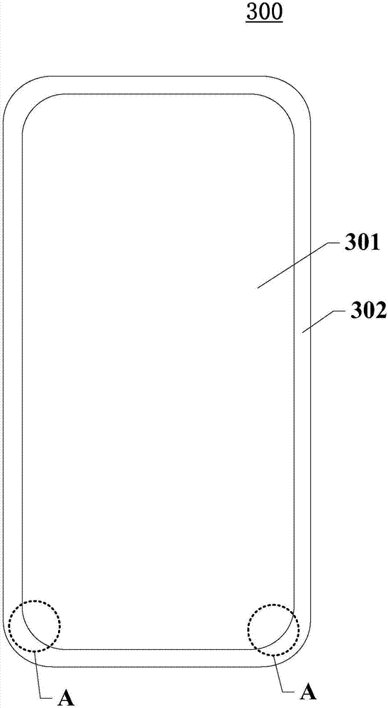
A technology for a display panel and a display area, which is applied to static indicators, digital memory information, instruments, etc., can solve the problems such as the reduction of the area of ​​the non-display area 302, the flickering of the display panel 300, and the tight layout space of the non-display area 302, etc. Achieve narrow border design, add additional functions, and improve display effects

Active Publication Date: 2018-05-04
SHANGHAI AVIC OPTOELECTRONICS
View PDF5 Cites 35 Cited by
  • Summary
  • Abstract
  • Description
  • Claims
  • Application Information

AI Technical Summary

Problems solved by technology

figure 1 A schematic structural view of a display panel in the prior art is shown. A rounded area A appears in the display area 301 of the display panel 300. In order to ensure the overall aesthetics of the display device, the non-display area 302 corresponding to the above-mentioned rounded area Special-shaped cutting is required, so that the area of ​​the non-display area 302 is reduced. At the same time, in order to realize the narrow frame design of the display panel, the area of ​​the non-display area 302 will be further reduced, which leads to the tight layout space of the non-display area 302. There will not be enough space on the panel 300 to place the static discharge circuit and other peripheral circuits. The static electricity generated during the manufacturing process of the display panel 300 will remain inside the display panel 300 and cannot be released, which will cause the display panel 300 to flicker during the display process. , Afterimages and other abnormal display phenomena greatly reduce the display effect of the display panel 300

Method used


Image

  • Display panel and display device
  • Display panel and display device
  • Display panel and display device

Examples


Embodiment Construction

[0028] Certain terms are used, for example, in the description and claims to refer to particular components. Those skilled in the art should understand that hardware manufacturers may use different terms to refer to the same component. The specification and claims do not use the difference in name as a way to distinguish components, but use the difference in function of components as a criterion for distinguishing. The subsequent description of the specification is a preferred implementation mode for implementing the application, but the description is for the purpose of illustrating the general principle of the application, and is not intended to limit the scope of the application. The scope of protection of the present application should be defined by the appended claims.

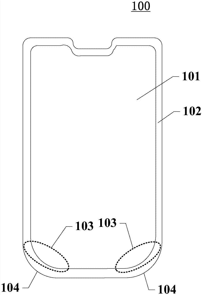
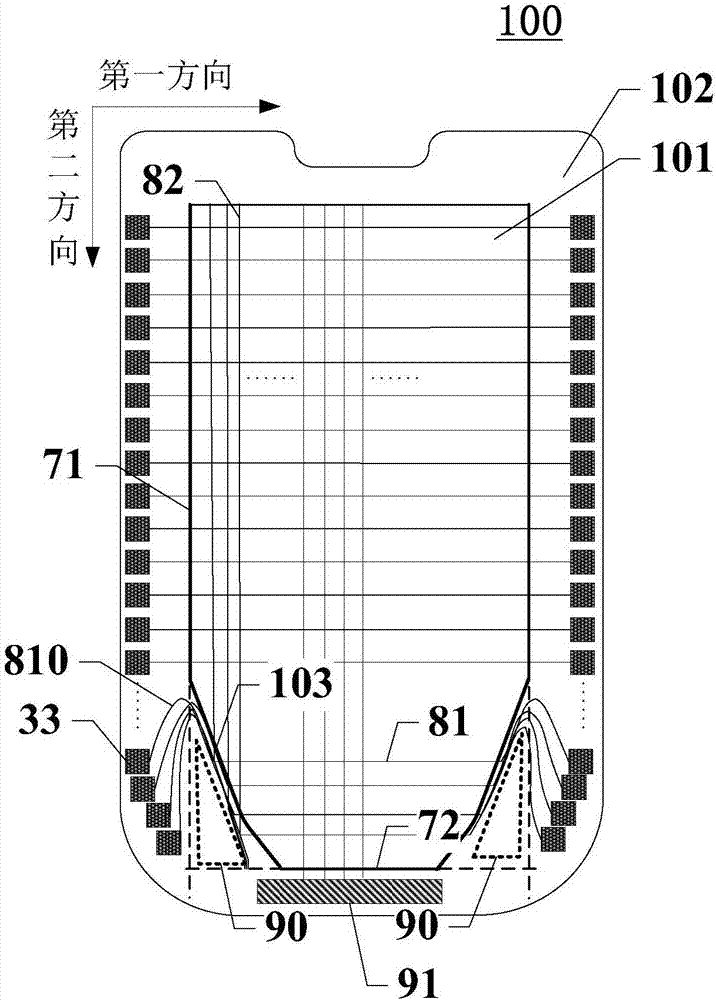
[0029] figure 2 Shown is a schematic diagram of the structure of the display panel provided by the embodiment of the present application, image 3 Shown is a schematic diagram of a circuit configurati...


PUM


Abstract

The invention discloses a display panel and a display device, and relates to the technical field of display. A display area of the display panel is provided with an arc boundary; the display panel includes a plurality of gate lines and a plurality of data signal lines, in the display area, the gate lines extend in a first direction and are distributed in a second direction, and all the data signallines are distributed in the first direction and extend in the second direction; a non-display area is provided with a plurality of gate driving circuits, and each gate driving circuit comprises a plurality of cascaded shift registers electrically connected with the corresponding gate lines respectively; the non-display area is further provided with a first circuit placement area located at the side, away from the display area, of the arc boundary; in the non-display area at the arc boundary, the gate lines led out from the shift registers wind from one side of the first circuit placement area to the display area; in the non-display area at the arc boundary, the data signal lines are located between the first circuit placement area and the display area. According to the scheme, the improvement of the display effect of the display panel and the display device is facilitated.

Description

technical field [0001] The present application relates to the field of display technology, in particular, to a display panel and a display device. Background technique [0002] With the development of science and technology, display devices with display panels are more and more widely used, making people's requirements for display panels more and more diversified, and they are no longer only satisfied with the large size and high definition of display panels. There are also more diversified requirements for the shape of the display panel, so there are special-shaped display panels. [0003] The emergence of the display panel has broken through the limitation of the single rectangular structure of the display panel, which not only makes the display effect more diversified, but also makes the application of the display panel more and more extensive, and has been successfully applied to such as watches, glasses or smart bracelets. in the design of wearable electronics. Compar...

Claims


Application Information

Patent Timeline
Patent Type & Authority Applications(China)
IPC IPC(8): G02F1/133G02F1/1343G02F1/1362G09G3/36G11C19/28
CPCG02F1/13306G02F1/134309G02F1/136204G02F1/136286G09G3/36G09G2310/0286G09G2320/0257G11C19/28
Inventor 金慧俊邵琬童
Owner SHANGHAI AVIC OPTOELECTRONICS
Why Eureka
Try Eureka