Laser driver circuit and laser display

a laser display and driver circuit technology, applied in the direction of laser details, color television details, semiconductor lasers, etc., can solve the problem of requiring a large amount of power, and achieve the effect of avoiding high power consumption

Inactive Publication Date: 2011-05-31
FUNAI ELECTRIC CO LTD
View PDF12 Cites 1 Cited by
  • Summary
  • Abstract
  • Description
  • Claims
  • Application Information

AI Technical Summary

Benefits of technology

[0015]An object of the present invention is to provide a laser driver circuit which can drive a laser diode without high power consumption, and a laser display which comprises the laser driver circuit.
[0020]The laser driver circuit further comprises a current output prevention circuit for preventing the voltage-to-current converter circuit from generating the current and preventing the current from being output from the current output line, when the current output line and the ground line are connected by the current path switch.
[0021]With the above configuration, when the current output line and the ground line are connected (when the voltage-to-current converter circuit does not supply the current to the laser diode), the current output prevention circuit can prevent the voltage-to-current converter circuit from generating the current so as to prevent the current from being output from the current output line. Thus, when the voltage-to-current converter circuit does not supply the current to the laser diode, the possibility can be reduced that an unnecessary current which does not contribute to the light emission of the laser diode is generated by the voltage-to-current converter circuit and flows to the ground. Accordingly, compared to a conventional laser driver circuit, the laser driver circuit can reduce power consumption, thereby can drive the laser diode with lower power consumption.
[0022]Preferably, the current supply circuit further comprises a voltage input line which is connected to the voltage-to-current converter circuit, and which inputs a voltage to the voltage-to-current converter circuit. Therein the current output prevention circuit further comprises a voltage input switch for switching between connection and disconnection of the voltage input line. And therein by disconnecting the voltage input line using the voltage input switch so that the voltage is not input to the voltage-to-current converter circuit, the current output prevention circuit prevents the voltage-to-current converter circuit from generating the current.
[0023]With this configuration, by a simple structure where the voltage input line is disconnected by the voltage input switch, the current output prevention circuit is realized. Furthermore, because the laser driver circuit employs the structure where the voltage input line is connected or disconnected by the voltage input switch, a current fall time and a current rise time of the current to be output from the current output line can be shortened, compared to the case where voltage-to-current convert function of the voltage-to-current converter circuit is halted or restarted. Thus, not only rapid control of the radiance of the laser beam to be emitted from the laser diode but also reducing power consumption can be realized.
[0033]The laser driver circuit further comprises a current output prevention circuit for preventing the voltage-to-current converter circuit from generating the current and preventing the current from being output from the current output line, when the current output line and the ground line are connected by the current path switch.

Problems solved by technology

Thus, the conventional laser driver circuit 100 generates and outputs wasteful currents which do not contribute to emission of the laser diode 101, and thereby requires a large amount of power.

Method used


Image

  • Laser driver circuit and laser display
  • Laser driver circuit and laser display
  • Laser driver circuit and laser display

Examples


Embodiment Construction

[0041]Referring now to the accompanying drawings, a preferred embodiment of the present invention is described. The present invention relates to a laser driver circuit which drives a laser diode, and a laser display which comprises the laser driver circuit. It is to be noted that the following description of preferred embodiment of the present invention has been presented for purposes of illustration and description, and is not intended to be exhaustive or to limit the present invention to the precise form disclosed.

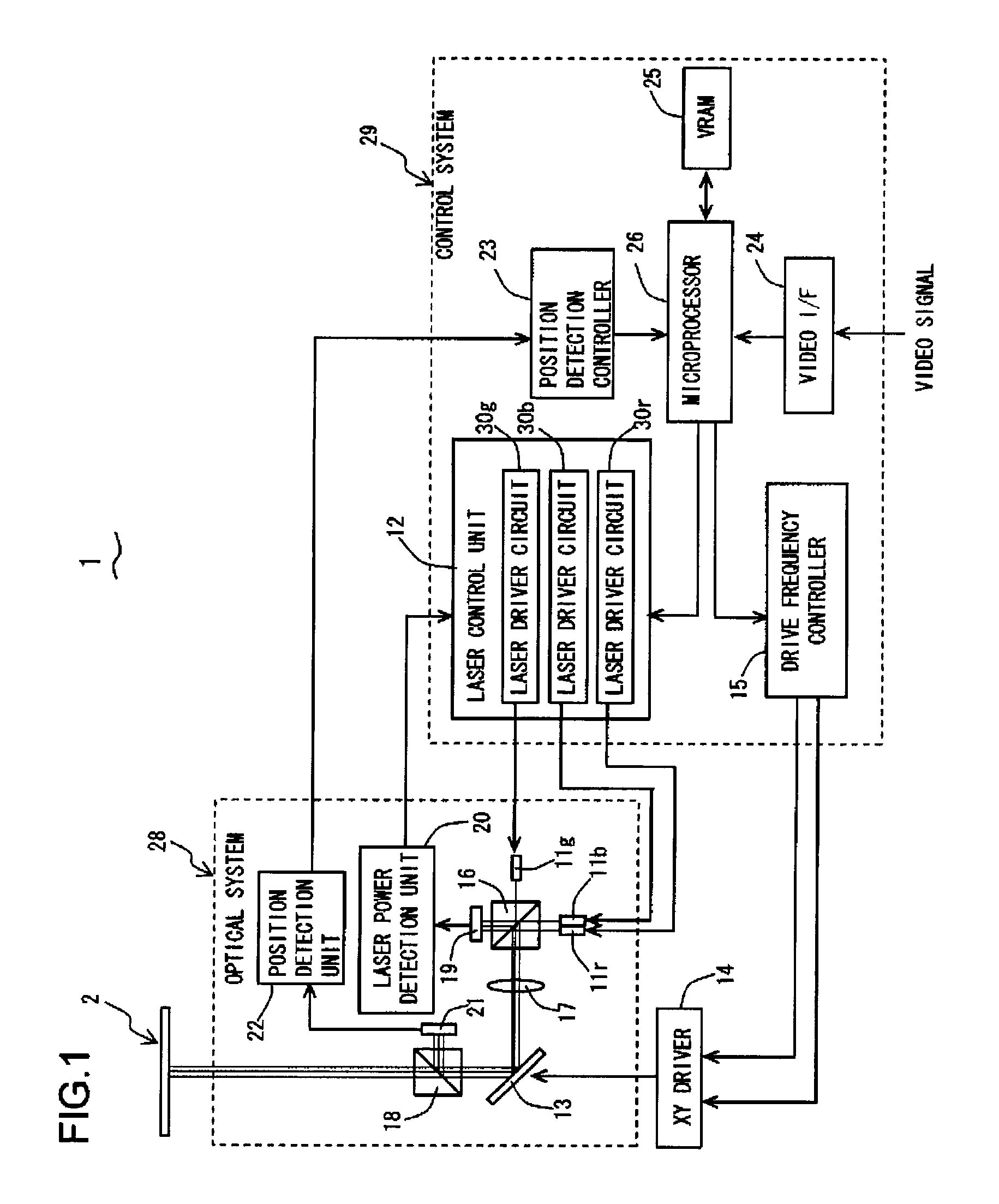
[0042]FIG. 1 shows a schematic block diagram of a laser display 1 which comprises laser driver circuits 30g, 30b, 30r according to this embodiment. The laser display 1 scans a laser beam across a screen 2 in order to display images on the screen 2.

[0043]The laser display 1 comprises laser diodes 11r, 11b, 11g which emit laser beams, a laser control unit 12 for controlling light emission of the laser diodes 11r, 11b, 11g, an XY scanning mirror 13 for scanning the laser be...


PUM


Abstract

A laser driver circuit comprising a current supply circuit for supplying a laser diode with a current is provided. The current supply circuit comprises a voltage-to-current converter circuit, a current output line for outputting the current generated by the voltage-to-current converter circuit, a current supply line connected to the laser diode, a ground line connected to the ground, and a current path switch for selectively connecting either the current supply line or the ground line to the current output line. The laser driver circuit further comprises a current output prevention circuit for preventing the voltage-to-current converter circuit from generating the current by disconnecting the voltage input line using a voltage input switch so that the voltage is not input to the voltage-to-current converter circuit, when the current output line and the ground line are connected by the current path switch.

Description

BACKGROUND OF THE INVENTION[0001]1. Field of the Invention[0002]The present invention relates to a laser driver circuit which drives a laser diode, and a laser display which comprises the laser driver circuit.[0003]2. Description of the Related Art[0004]Conventionally, there is known a laser display which scans a laser beam across a screen in order to display images on the screen. The laser display comprises a laser driver circuit for driving a laser diode. The laser display drives a laser diode with the laser driver circuit so as to irradiate the screen with the laser beam. FIG. 5 illustrates an example of a conventional laser driver circuit.[0005]A laser driver circuit 100 shown in FIG. 5 is a current drive type laser driver circuit which drives a laser diode 101 by supplying the laser diode 101 with a current. In order to drive the laser diode 101, the laser driver circuit 100 supplies the laser diode 101 with not only a threshold current from a current supply circuit 140-0 for s...

Claims


Application Information

Patent Timeline
Patent Type & Authority Patents(United States)
IPC IPC(8): H01S3/00
CPCH01S5/042H04N9/3155H04N9/3129H01S5/0428
Inventor NISHIOKA, KENNAGASHIMA, KENJIHIRANO, ATSUYACHIKAOKA, ATSUHIKO
Owner FUNAI ELECTRIC CO LTD
Why Eureka
Try Eureka