Cluster system and failover method for cluster system

Inactive Publication Date: 2008-07-03
HITACHI LTD
View PDF10 Cites 81 Cited by
  • Summary
  • Abstract
  • Description
  • Claims
  • Application Information

AI Technical Summary

Benefits of technology

[0007]According to the method 1, by monitoring failures of the guest OS and the AP through communication (heartbeat), the cluster program between the guest OS's executes failover to a standby system when a failur

Problems solved by technology

Thus, there is a first problem that heartbeats are delayed.
Thus, the cluster program in the standby system guest OS becomes idle in other than failure monito

Method used


Image

  • Cluster system and failover method for cluster system
  • Cluster system and failover method for cluster system
  • Cluster system and failover method for cluster system

Examples


first embodiment

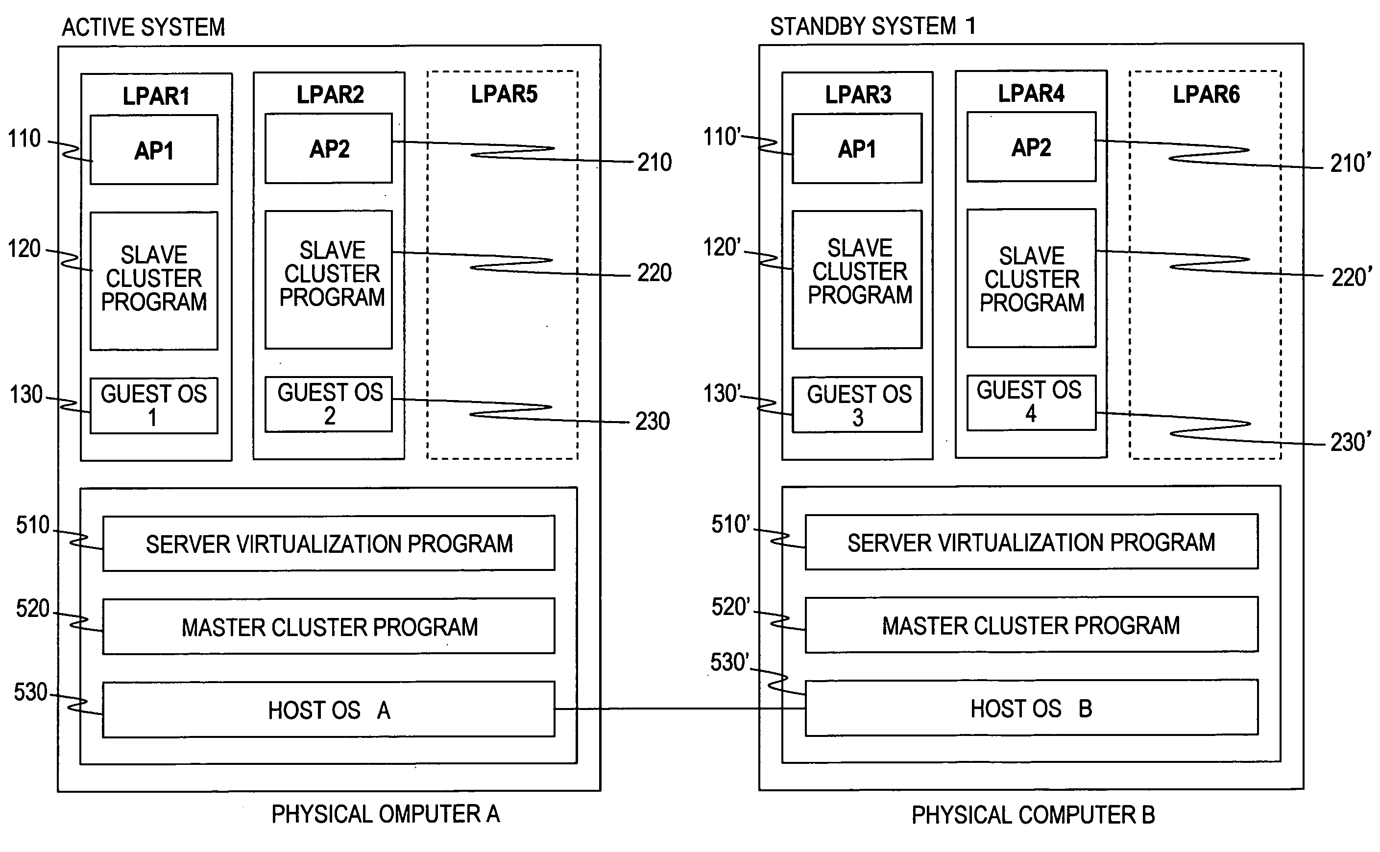
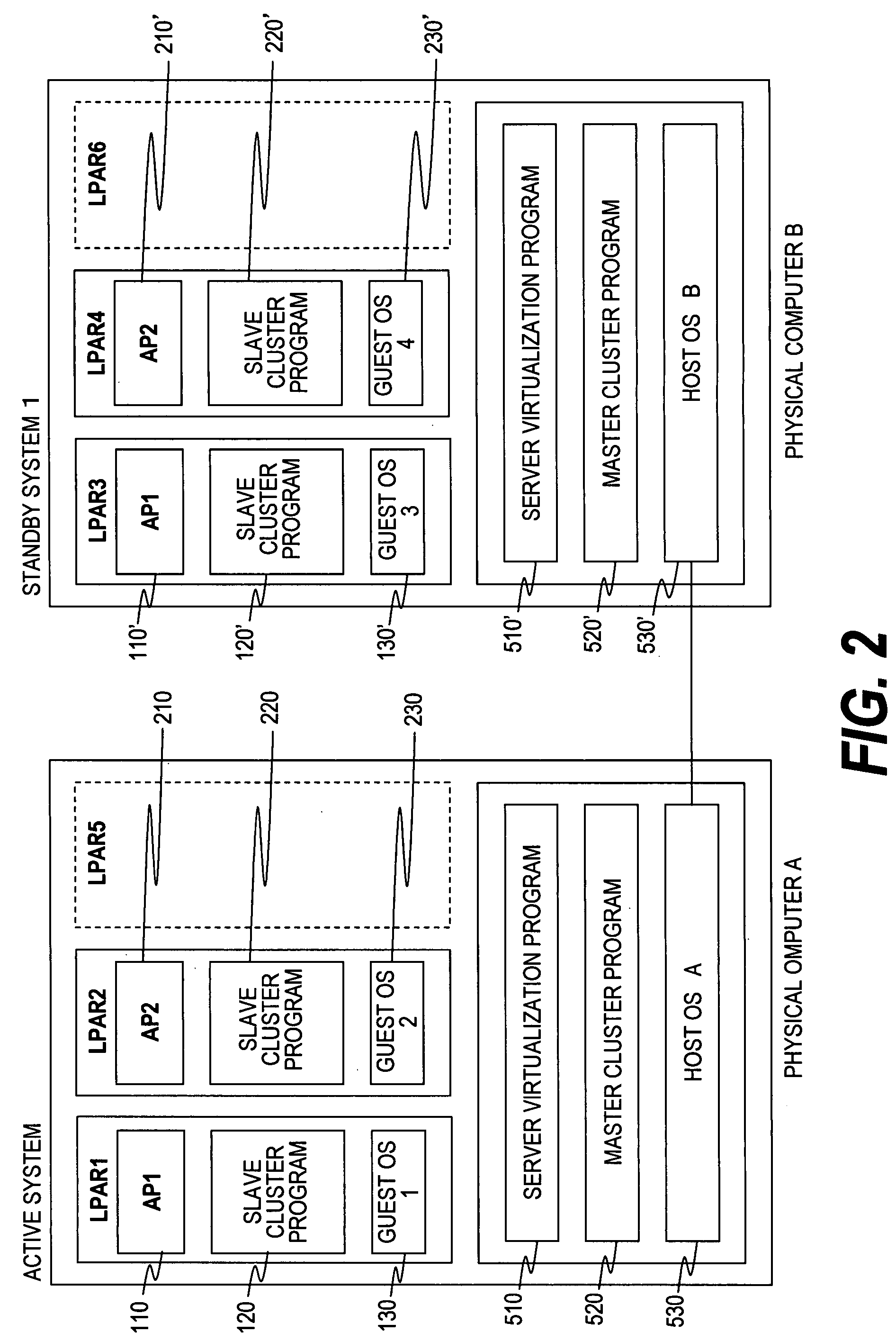
[0075]It should be noted that drawings and description of this invention are simplified to show proper elements for clearly understanding this invention, and well-known elements and the like are omitted as long as it does not hinder implementation of this invention. In the technology of this invention, there are some other elements of the conventional art desired and / or necessary for implementing this invention. However, as those elements of the conventional art are well-known, and are not necessary for facilitating understanding of this invention, they will not be explained. In the description below, programs may be described based on module numbers of an active system (or current system), but the description thereof may also serves as description of corresponding programs in a standby system. Further, in reference symbols shown below, some may use symbols identical to those shown in the other drawings, and denote similar components unless specified otherwise.

[0076]FIGS. 1 to 9 sho...

second embodiment

[0121]FIG. 10 is a flowchart showing a second embodiment which is partially changed from the first embodiment of FIG. 9. Other components are similar to those of the first embodiment.

[0122]In FIG. 10, a master cluster program 520 of an active system executes processing 4A of FIG. 10, and executes steps S401 and S402 of FIG. 10 as in the case of the steps S301 and 302 of FIG. 9 to transmit a notification T13 of a guest OS state.

[0123]A master cluster program 520′ of a standby system executes processing 3B of FIG. 10, and judges whether the notification T13 has been received from the master cluster program 520 of the active system as in the case of the step S341 (S441). If the notification T13 has been received, as in the case of the step S345 of FIG. 9, according to received contents, the master cluster program 520′ of the standby system updates management tables 525 and 513 (S444), and returns again to the step S441 to wait for a heartbeat from a host OS.

[0124]On the other hand, if ...

third embodiment

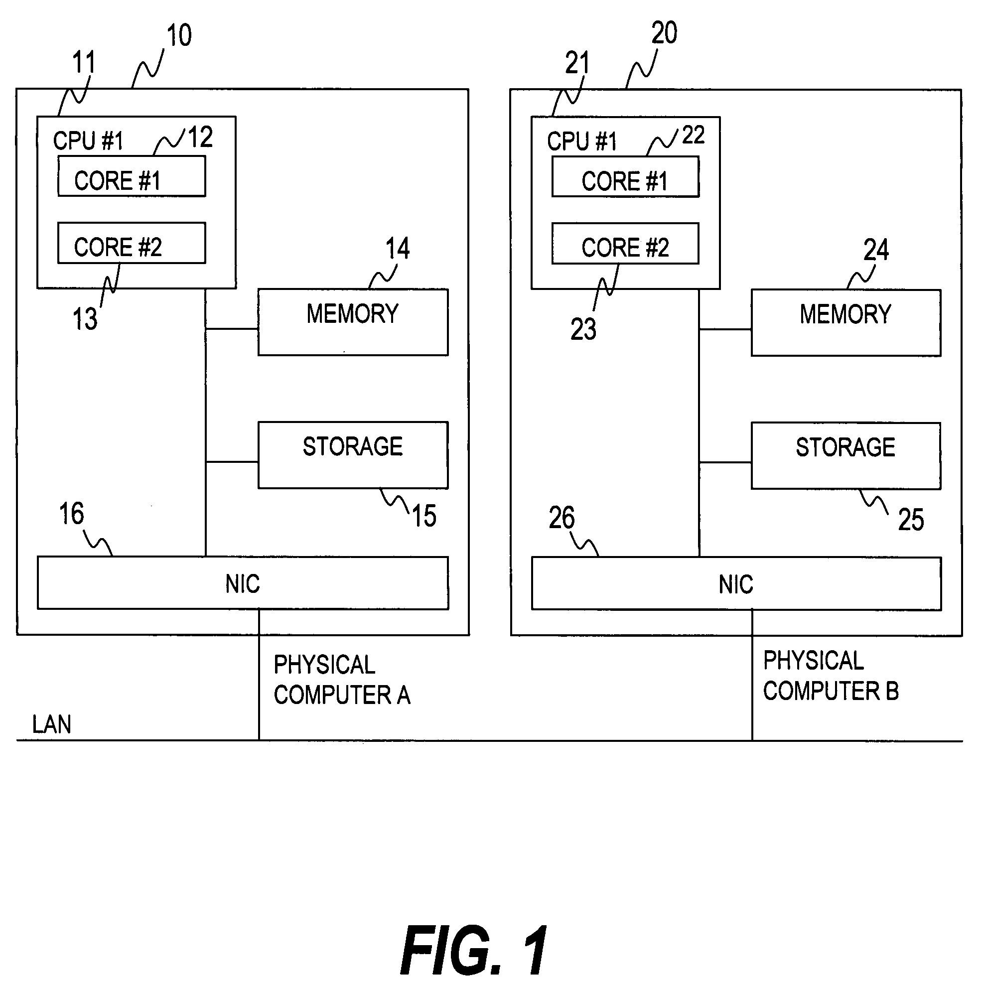
[0129]FIGS. 11 to 15 show a third embodiment. FIG. 11 is a functional block diagram of a physical computer A according to the third embodiment of this invention.

[0130]In FIG. 11, in addition to the components of the first embodiment shown in FIG. 3, the master cluster program 520 includes an application state management unit 526 for obtaining an application state from the slave cluster program 120 to monitor the application state. Because a standby system is configured as in the case of an active system, the standby system is not shown in the drawings.

[0131]The application state management unit 526 includes an application state management table 527 shown in FIG. 12. In FIG. 12, the application state management table 527 contains an application identifier 4001 of an application which is a monitoring target of the slave cluster program 120, a system state 4002 indicating an active system or a standby system as a role of the application identifier 4001 in a cluster, a host OS identifie...


PUM


Abstract

Provided is a failover method for a cluster system for realizing smooth failover of the guest OS's, even when there are many guest OS's, while reducing consumption of computer resources of a server. Smooth failover is realized by preventing competition during failover even when the number of guest OS's is increased. In a cluster configuration in which a slave/master cluster program is operated in a guest OS/host OS, the master cluster program (510) collects and transmits heartbeats of the slave cluster program, thereby realizing failure monitoring through the certain amount of heartbeats without depending on the number of guest OS's. Further, when the master cluster program monitors failures of the slave cluster program of its own computer to find a normal operation of the guest OS, the amount of communication through heartbeats is reduced by eliminating the necessity of communication to a standby system slave cluster program.

Description

CLAIM OF PRIORITY[0001]The present application claims priority from Japanese application P 2006-356576 filed on Dec. 28, 2006, the content of which is hereby incorporated by reference into this application.BACKGROUND OF THE INVENTION[0002]This invention relates to a highly available computer system which constitutes a cluster configuration in a server virtualization environment, and more particularly to a program which has a function of monitoring failures and executing failover.[0003]Server virtualization is a technology of simultaneously operating a plurality of operating systems (hereinafter, referred to as OS) in a single physical computer. Logical partitioning is realized via a management program (server virtualization program) for dividing resources of the physical computer into a plurality of logical partitions (LPAR), and one OS (guest OS) is operated in each LPAR. The server virtualization program is a program operated in a server virtualization layer (hereinafter, referred...

Claims


Application Information

Patent Timeline
IPC IPC(8): G06F11/07
CPCG06F11/0712G06F11/0757G06F11/2028G06F11/1484G06F11/2097G06F2201/815G06F11/1482G06F11/2048
Inventor BABA, TSUNEHIKOTSUSHIMA, YUJIMORIKI, TOSHIOMI
Owner HITACHI LTD
Why Eureka
Try Eureka