Ptychography based system and method

a technology of ptychography and system, applied in the field of ptychography based system and method, can solve the problems of limited frame rate increase using ccd or cmos technology, complicated ultrahigh-speed cameras or microscopes,

Active Publication Date: 2020-05-07
TECHNION RES & DEV FOUND LTD
View PDF0 Cites 6 Cited by
  • Summary
  • Abstract
  • Description
  • Claims
  • Application Information

AI Technical Summary

Problems solved by technology

This is because imaging of non-repetitive ultrafast dynamical objects requires complicated ultrahigh-speed cameras or microscopes (as compared to the known pump-probe techniques employed for exploring repetitive ultrafast events).
Further increase in the frame rate using CCD or CMOS technology is limited by their on-chip storage and electronic readout speed.

Method used


Image

  • Ptychography based system and method
  • Ptychography based system and method
  • Ptychography based system and method

Examples


Embodiment Construction

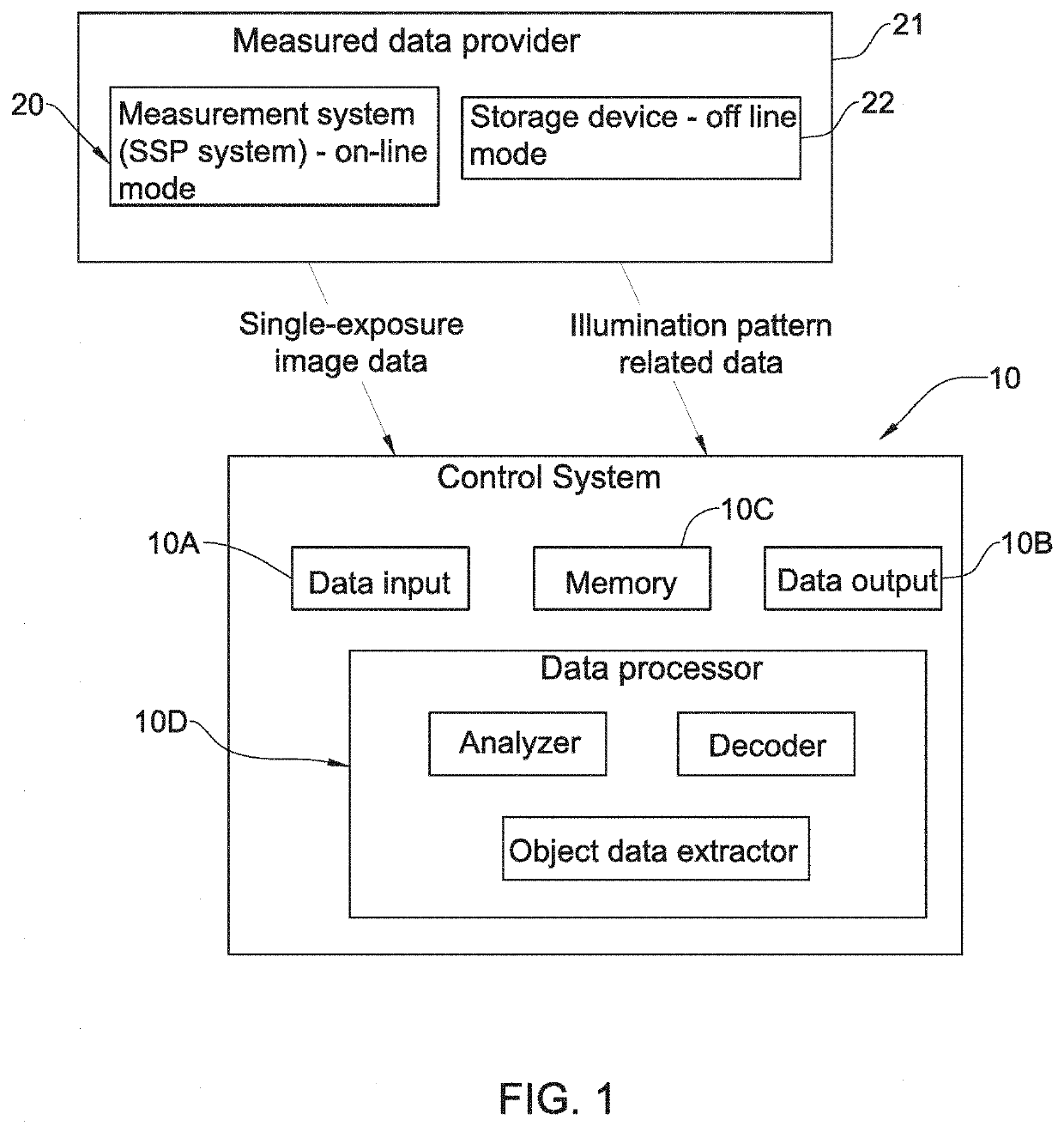
[0069]Reference is made to FIG. 1, which illustrates, by way of a block diagram, a control system 10 configured and operable according to the invention for receiving and processing image data obtained by an SSP imaging system 20 of the invention utilizing the concept of TIMP technique. The control system 10 is typically a computer system comprising such main hardware / software utilities as data input 10A, data output 10B, memory 10C, and data processor 10D. It should be understood that image data to be processed by the control system 10 is received from / provided by a measured data provider 21, which may be the SSP system 20 itself (on-line object reconstruction mode) and / or a storage device 22 (off-line operational mode), which may be either a separate device or a part of the SSP system. The computer system 10 may thus be configured for data communication (e.g. via a communication network) with the measured data provider 30.

[0070]The data processor 10D is configured and operable to p...


PUM


Abstract

A ptychography system is presented for imaging an object located in an object plane. The ptychography system comprises an optical system, and a detection device. The optical system comprises a single shot ptychography arrangement configured and operable to create light response patterns from the object in the object plane on a pixel matrix of the detection device during the same exposure session of the detection device, wherein the optical system further comprises at least one light coding device configured and operable to apply at least one predetermined coding function to at least one of illuminating light and the light response of the object being collected, and said detection device is configured and operable with a predetermined duration of the exposure session during which the pixel matrix detects the collected light, such that image data indicative of the detected light during a single exposure session is in the form of a coded light response of the object being illuminated.

Description

TECHNOLOGICAL FIELD[0001]The present invention is in the field of imaging techniques, and is specifically relevant for imaging of non-repetitive ultrafast dynamical objects.BACKGROUND ART[0002]References considered to be relevant as background to the presently disclosed subject matter are listed below:[0003]1. K. Nakagawa, A. Iwasaki, Y. Oishi, R. Horisaki, A. Tsukamoto, A. Nakamura, K. Hirosawa, H. Liao, T. Ushida, K. Goda, F. Kannari, and I. Sakuma, “Sequentially timed all-optical mapping photography (STAMP),” Nat. Photonics 8(9), 695-700 (2014).[0004]2. L. Gao, J. Liang, C. Li, and L. V. Wang, “Single-shot compressed ultrafast photography at one hundred billion frames per second,” Nature 516(7529), 74-77 (2014).[0005]3.10. X. Chen, J. Wang, M. Versluis, N. de Jong, and F. S. Villanueva, “Ultra-fast bright field and fluorescence imaging of the dynamics of micrometer-sized objects,” Rev. Sci. Instrum. 84(6), 063701 (2013).[0006]4. K. Goda, K. K. Tsia, and B. Jalali, “Amplified disp...

Claims


Application Information

Patent Timeline
Patent Type & Authority Applications(United States)
IPC IPC(8): G02B21/36G02B21/00
CPCG02B21/0032G02B21/367G02B21/0084G02B21/086G02B21/361G02B27/46G02B27/58
Inventor COHEN, ORENILAN HAHAM, GILSIDORENKO, PAVELLAHAV, ORENPELEG, ORCHEN, BING KUAN
Owner TECHNION RES & DEV FOUND LTD
Why Eureka
Try Eureka