Brake controller

a technology of brake controller and brake pedal, which is applied in the direction of brake system, brake components, transportation and packaging, etc., can solve the problems of incongruity feeling of the driver, and achieve the effect of improving the brake feeling, and suppressing the incongruity feeling

Active Publication Date: 2020-07-30
ADVICS CO LTD +1
View PDF23 Cites 1 Cited by
  • Summary
  • Abstract
  • Description
  • Claims
  • Application Information

AI Technical Summary

Benefits of technology

[0004]Here, in a case where the deceleration of the vehicle is changed by control, not by the braking operation of a driver, the driver may feel different brake feelings with respect to the same braking operation. The driver may feel a sense of incongruity when the weight is changed with respect to the same braking operation. On the other hand, there may be a case where the brake feeling can be improved by changing the weight depending on a vehicle condition.
[0005]The present invention has been made in view of the above circumstances, and an object thereof is to provide a brake controller capable of suppressing the sense of incongruity given to the driver during braking.
[0006]A brake controller according to the present disclosure that changes an effect correlation value correlating to an effect of braking in a first braking system provided in a vehicle in accordance with a vehicle condition of the vehicle includes a control part generating a braking force by at least one of the first braking system and a second braking system different from the first braking system in a case where the vehicle condition is a first condition based on a braking distribution ratio different from that in a case where the vehicle condition is a second condition, and a setting part setting the effect correlation values so as to be different from each other in the case where the vehicle condition is the first condition and in the case where the vehicle condition is the second condition.
[0007]According to the present disclosure, the braking distribution ratio is changed in the first braking system and the second braking system in a case where the vehicle condition is changed between the first condition and the second condition. Then, the effect correlation value is changed so as to correspond to the timing when the braking distribution ratio is changed. A change in a brake feeling generated by changing the effect correlation value can be diverted by a change in the brake feeling generated by changing the braking distribution ratio that is originally allowed for the driver. Accordingly, the driver does not easily feel the change in the brake feeling due to the change of the effect correlation value. According to the present disclosure, it is possible to suppress the sense of incongruity given to the driver by the change of the effect correlation value.

Problems solved by technology

The driver may feel a sense of incongruity when the weight is changed with respect to the same braking operation.

Method used


Image

  • Brake controller
  • Brake controller

Examples


Embodiment Construction

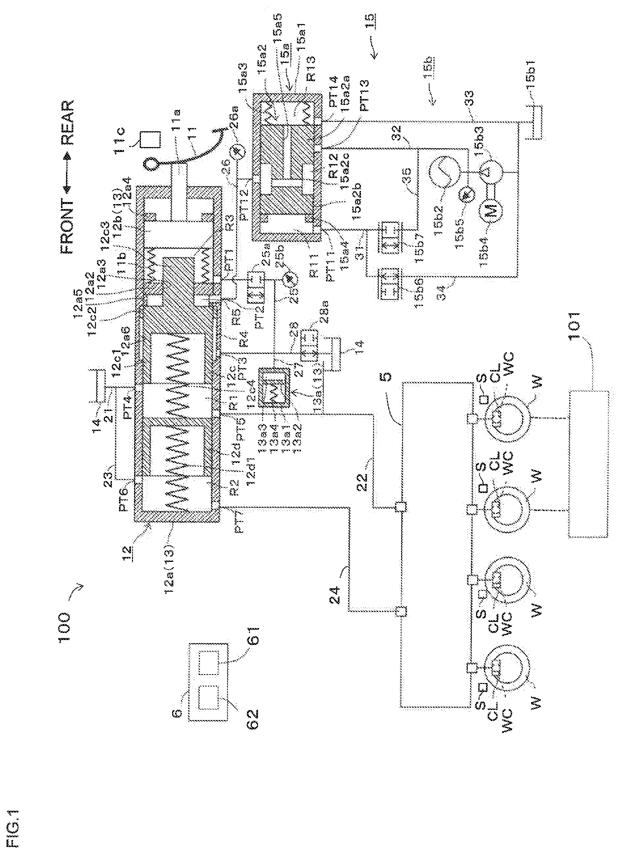
[0010]Hereinafter, an embodiment of the present disclosure will be explained with reference to the drawings. Respective drawings used for explanation are conceptual diagrams. A vehicle is provided with a hydraulic braking system (corresponding to a “first braking system”) 100 braking the vehicle by applying hydraulic braking forces to respective wheels W. The vehicle is also provided with a regenerative braking system (corresponding to a “second braking system) 101 applying regenerating braking forces to front wheels W and / or rear wheels W. Note that wheel speed sensors S are provided in respective wheels W.

[0011]The hydraulic braking system 100 is a system applying the hydraulic braking forces corresponding to hydraulic pressures inside wheel cylinders WC to the wheels W. Specifically, the hydraulic braking system 100 includes a brake pedal 11, a master cylinder 12, a stroke simulator part 13, a reservoir 14, a booster mechanism 15, an actuator 5, a brake ECU 6, and the wheel cylin...


PUM


Abstract

A brake controller according to the present disclosure that changes an effect correlation value correlating to an effect of braking in a first braking system provided in a vehicle in accordance with a vehicle condition of the vehicle includes a control part generating a braking force by at least one of the first braking system and a second braking system different from the first braking system in a case where the vehicle condition is a first condition based on a braking distribution ratio different from that in a case where the vehicle condition is a second condition and a setting part setting the effect correlation values so as to be different from each other in the case where the vehicle condition is the first condition and in the case where the vehicle condition is the second condition.

Description

CROSS REFERENCE TO RELATED APPLICATIONS[0001]Priority is claimed on Japanese application No. 2019-010760, filed Jan. 25, 2019 the content of which is incorporated herein by reference.BACKGROUND OF THE INVENTIONTechnical Field[0002]The present invention relates to a brake controller.Background Art[0003]The brake controller sets a target deceleration, for example, in accordance with an operation of a brake pedal, and controls a braking system based on the target deceleration. Here, in a brake controller described in, for example, JP-A-2000-229564, a weight is changed in accordance with driving states of a vehicle such as a high-speed running state, a mountain running state or a traffic-jam running state to change the deceleration.SUMMARY OF THE INVENTION[0004]Here, in a case where the deceleration of the vehicle is changed by control, not by the braking operation of a driver, the driver may feel different brake feelings with respect to the same braking operation. The driver may feel a...

Claims


Application Information

Patent Timeline
Patent Type & Authority Applications(United States)
IPC IPC(8): B60T13/66B60W20/14B60T8/32B60W10/188B60W10/192
CPCB60T13/662B60T8/3265B60W10/192B60W10/188B60W10/182B60W20/14B60T7/042B60T8/17B60T8/409B60T8/44B60T8/4081B60T2270/604B60T1/10F16D57/04B60W10/08B60W30/18127
Inventor KUBOTA, HAYATONAKATA, DAISUKE
Owner ADVICS CO LTD
Why Eureka
Try Eureka