Disc brake for a vehicle

a disc brake and disc technology, applied in the direction of braking discs, braking systems, braking components, etc., can solve the problems of increasing the weight and the size of the caliper bracket, deteriorating the brake feeling, and partially abraded frictional pads, etc., to suppress frictional pads and enhance the brake feeling.

Active Publication Date: 2005-10-06
HITACHI ASTEMO LTD
View PDF5 Cites 10 Cited by
  • Summary
  • Abstract
  • Description
  • Claims
  • Application Information

AI Technical Summary

Benefits of technology

[0009] Therefore, it is one of objects of the present invention to provide a disc brake for a vehicle that while the increases in the weight and the size of a caliper bracket are being suppressed, a tilt and a twist of the caliper bracket in the axial direction of the disc rotor are effectively suppressed at the time of braking so that the brake feeling can be enhanced and it is possible to suppress the frictional pads from being partially abraded and disadvantageously dragged.

Problems solved by technology

Accordingly, the brake feeling is deteriorated.
Further, there is a possibility that the frictional pads are partially abraded and disadvantageously dragged.
Therefore, in the related art, the wall thickness of the caliper bracket must be increased, which increases the weight and the size of the caliper bracket.
As a result, the manufacturing cost of the disc brake is raised.
Therefore, when the disc brake is used in a condition in which earth and sand tend to get into the periphery of the disc brake, the earth and sand, which have gotten into the periphery of the friction pad, are caught by the complicated recess portions and protruding portions.
In this case, although it is a temporary phenomenon, the friction pad bites the earth and sand, and the brake feeling is deteriorated and further the dragging of the friction pad occurs.

Method used


Image

  • Disc brake for a vehicle
  • Disc brake for a vehicle
  • Disc brake for a vehicle

Examples


Embodiment Construction

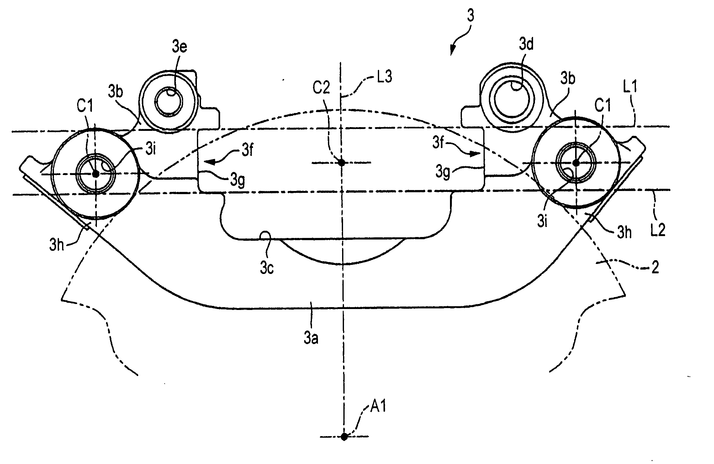
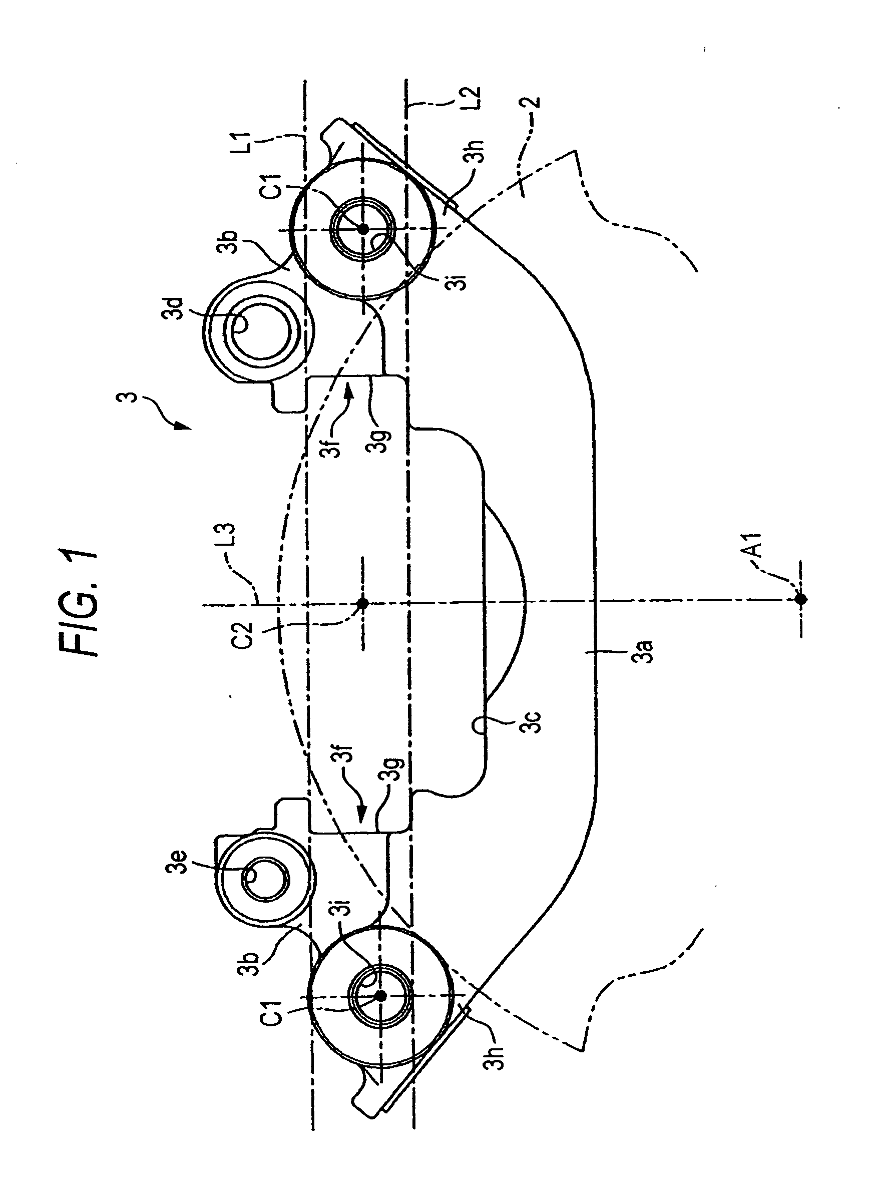
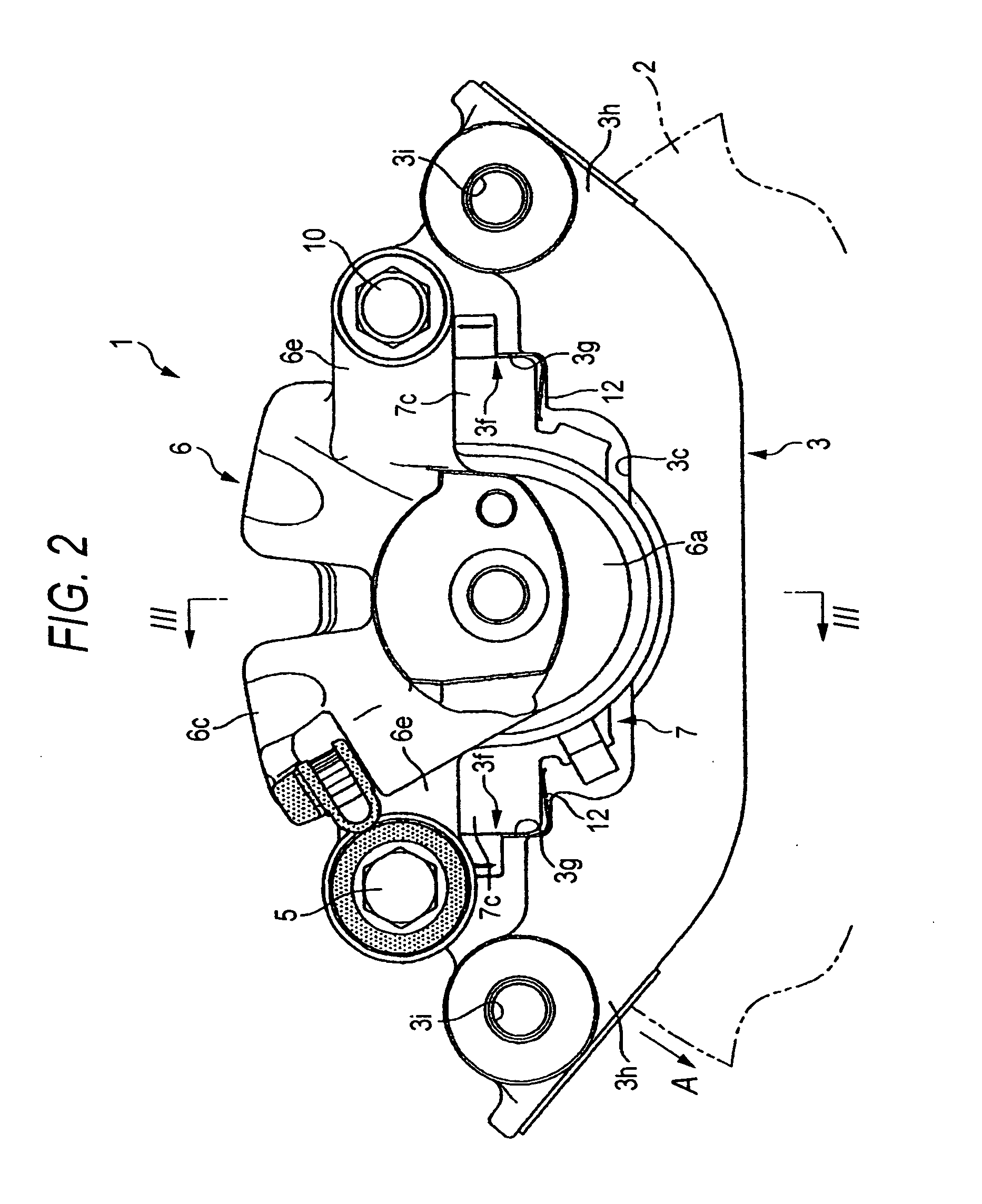
[0067] Referring to the drawings, the first embodiment of the present invention will be explained in detail as follows. FIGS. 1 to 6 are views showing the first embodiment of the disc brake for a vehicle of the present invention. FIG. 1 is a front view of the caliper bracket, FIG. 2 is a front view of the disc brake, FIG. 3 is a sectional view taken on line III-III in FIG. 2, FIG. 4 is a sectional view taken on line IV-IV in FIG. 3, FIG. 5 is a rear view of the disc brake, and FIG. 6 is a partially sectional plan view of the disc brake. Arrow A in the drawing shows a direction of the rotation of the disc rotor at the time when the vehicle runs forward. The rotation come-in side and the rotation come-out side of the disc brake used in the following explanations show a case in which the vehicle runs forward.

[0068] In a disc brake 1, a caliper bracket 3 is fixed to a vehicle body 6 on one side of a disc rotor 2, and the caliper body 6 is supported by the caliper bracket 3 via slide pi...


PUM


Abstract

A disc brake for a vehicle has a caliper body including an acting section having a cylinder hole and provided on a first side of a disc rotor, a reacting section on a second side of the disc rotor and a bridge section connecting the acting section with the reacting section, a pair of friction pads, a caliper bracket fixed to a vehicle body via a pair of mounting bolts, the caliper bracket having a mount hole for the mounting bolt and a torque receiving face and provided on both sides of the caliper bracket in a circumferential direction of the disc rotor and a pair of slide pins wherein a center of the mount hole of the mounting bolt and a center of the cylinder hole are located in an area defined between the first and second base lines.

Description

[0001] The present invention claims foreign priority to Japanese patent applications no. P.2004-97668 and P.2004-99515, filed on Mar. 30, 2004, the contents of which are incorporated herein by references. BACKGROUND OF THE INVENTION [0002] 1. Field of the Invention [0003] The present invention relates to a disc brake for a vehicle incorporated into an automobile or motorcycle. More particularly, the present invention relates to a pin-slide type disc brake for a vehicle. [0004] 2. Description of the Related Art [0005] The pin-slide type disc brake is typically composed as follows. A caliper body, to which an acting section provided on one side of a disc rotor and a reacting section provided on the other side of the disc rotor are integrally connected by a bridge portion which strides across the outside of the disc rotor, is supported by a caliper bracket, which is fixed to a vehicle body at one side portion of the disc rotor, by a pair of slide pins so that the caliper body can slide...

Claims


Application Information

Patent Timeline
Patent Type & Authority Applications(United States)
IPC IPC(8): B60T1/06B60T17/00F16D55/00F16D55/226F16D55/227F16D65/02F16D65/092F16D65/095
CPCF16D55/22655F16D2055/0008F16D55/227
Inventor IWASAKI, MASARU
Owner HITACHI ASTEMO LTD
Why Eureka
Try Eureka