Radially mounted disk brake

a disk brake and radial mounting technology, applied in the direction of braking components, actuators, braking elements, etc., can solve the problems of brake judder, brake damage, impaired brake feeling, etc., to reduce the movement of the caliper body, reduce the effect of brake judder and small valu

Active Publication Date: 2005-03-10
HONDA MOTOR CO LTD +1
View PDF3 Cites 8 Cited by
  • Summary
  • Abstract
  • Description
  • Claims
  • Application Information

AI Technical Summary

Benefits of technology

[0011] In an arrangement where the large-diameter hole portions are formed at the support member-side openings of the mounting holes of the caliper body, they are fitted with the side wall surfaces of the cylindrical step portions provided on the support member, thereby restricting the movement of the caliper body, i.e. the caliper, during braking. Therefore, it is possible to minimize brake judder due to the movement of the caliper relative to the support member even if the tightening torque applied to the mounting bolts is reduced to a relatively small value. Accordingly, the deformation of the cylinder bore is minimized, and favorable sliding performance of the piston can be obtained. Thus, brake feeling improves. In an arrangement where the large-diameter hole portions have gaps between their bottoms and the distal end surfaces of the cylindrical step portions, the deformation of the caliper body toward the cylinder bore due to the tightening torque applied to the mounting bolts can be absorbed by the gaps. As a result, the deformation of the cylinder bore is further minimized. Accordingly, favorable sliding performance of the piston can be surely obtained. Thus, brake feeling improves surely. In an arrangement where the center of the axial length of each mounting hole of the caliper body, at which deformation occurring outward of the mounting hole due to the tightening torque reaches a maximum, is positioned radially outward of the disk rotor in the axial direction of the mounting hole with respect to a thin-walled shortest-distance portion of the caliper body at which the distance between the center of the cylinder bore and the mounting hole is shortest, the structure reduces the degree of influence on the cylinder bore of the deformation of the caliper body toward the cylinder bore due to the tightening torque. As a result, the deformation of the cylinder bore is further minimized, and favorable sliding performance of the piston can be obtained even more surely. Accordingly, brake feeling improves even more surely.

Problems solved by technology

This may cause the part of the caliper to be damaged.
Therefore, it is likely that braking torque acting on the caliper during braking may cause the abutting surfaces to be relatively displaced in the axial direction of the disk rotor, and, consequently, the caliper may vibrate, causing brake judder.
The deformation of the cylinder bore deteriorates the sliding performance of a piston sliding in the cylinder bore, resulting in impaired brake feeling.
Consequently, brake feeling will be further impaired.

Method used


Image

  • Radially mounted disk brake
  • Radially mounted disk brake
  • Radially mounted disk brake

Examples


Embodiment Construction

[0016] A radially mounted disk brake according to one embodiment of the present invention will be described below with reference to the accompanying drawings.

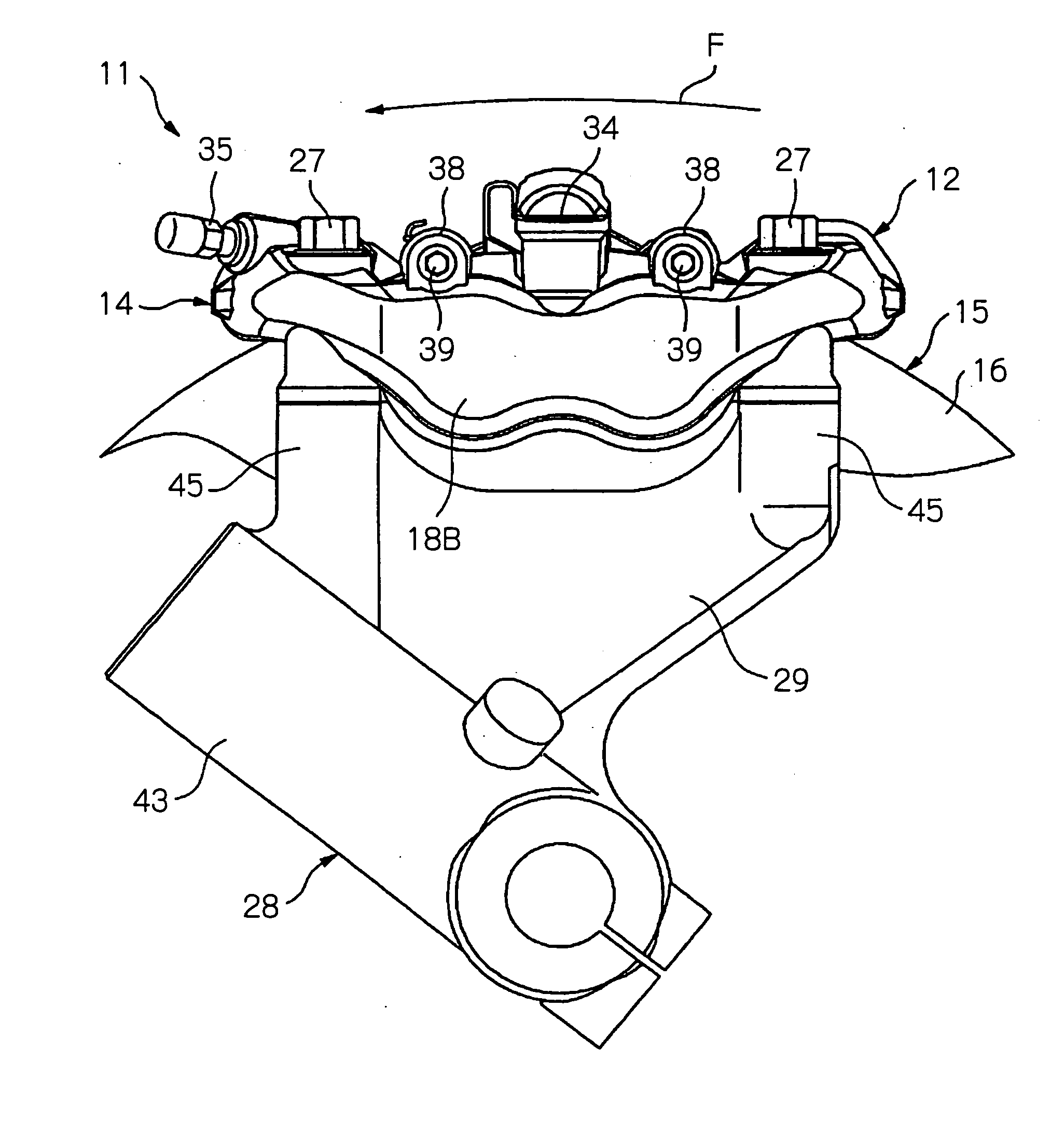
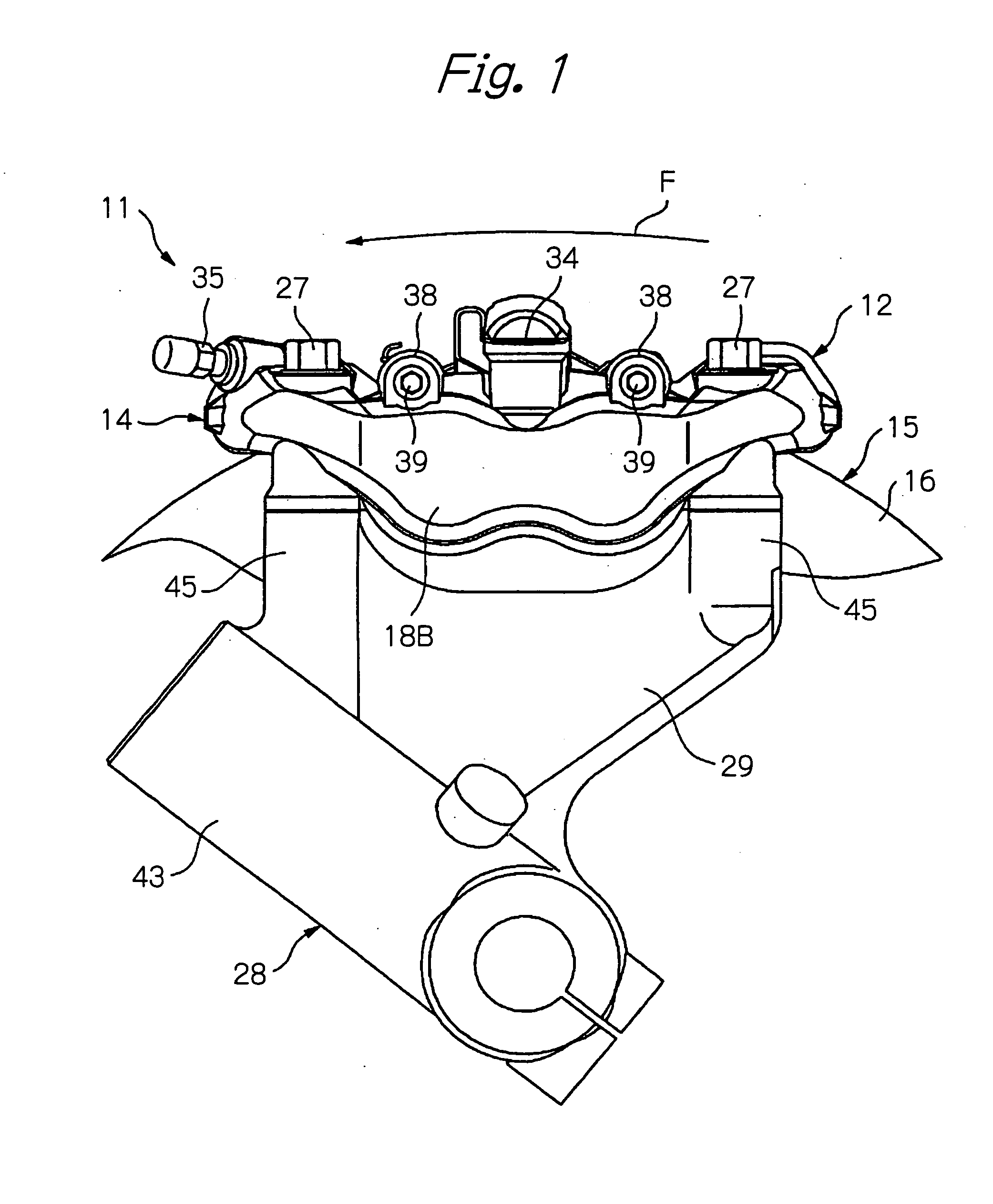
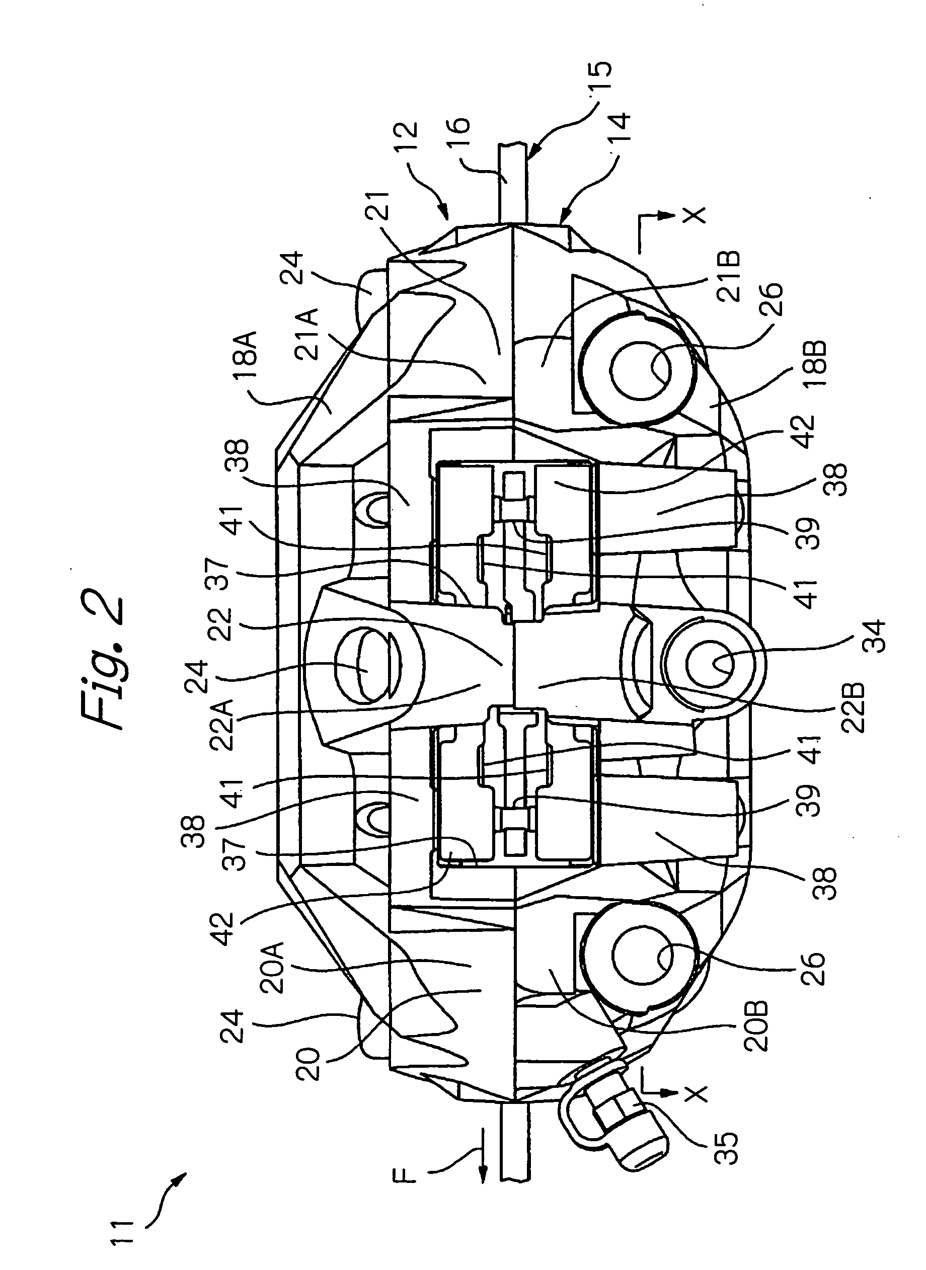
[0017] As shown in FIG. 1, the radially mounted disk brake 11 according to this embodiment is a fixed caliper type disk brake having a caliper 12 fixed to a member on a vehicle body. A caliper body 14 constitutes an essential part of the caliper 12. As shown in FIG. 2, the caliper body 14 has an inner caliper half 18A disposed at the axially inner side (relative to the vehicle) of a disk portion 16 forming braking surfaces of a disk rotor 15 that rotates together with a wheel (not shown) as one unit. The caliper body 14 further has an outer caliper half 18B disposed at the axially outer side of the disk portion 16 (relative to the vehicle). The inner caliper half 18A and the outer caliper half 18B are butt-joined together as one unit. It should be noted that the terms “inner” and “outer” are used herein on the basis of the lay...


PUM


Abstract

A radially mounted disk brake has a caliper body secured to a support member secured to a vehicle body. The caliper body has mounting holes extending in a direction perpendicular to the axis of rotation of a disk rotor. Large-diameter hole portions are formed at the openings of the mounting holes on the side thereof closer to the support member. The large-diameter hole portions are fitted with the side wall surfaces of cylindrical step portions provided on the support member in such a manner that gaps are formed between the bottoms of the large-diameter hole portions and the distal end surfaces of the step portions. The center of the axial length of each mounting hole is positioned radially outward of the disk rotor in the axial direction of the mounting hole with respect to a shortest-distance portion of the caliper body at which the distance between the center of a cylinder bore and the mounting hole is shortest.

Description

BACKGROUND OF THE INVENTION [0001] The present invention relates to a radially mounted disk brake used to brake a vehicle. [0002] A known radially mounted disk brake includes a caliper having a plurality of mounting holes extending in a direction perpendicular to the axis of rotation of a disk rotor. The caliper is secured to a support member fixed to a vehicle body with mounting bolts passed through the mounting holes. In the radially mounted disk brake, when the caliper is secured to the support member on the vehicle body, tightening torque applied to the mounting bolts acts on a part of the caliper. This may cause the part of the caliper to be damaged. For the purpose of preventing such a problem, a conventional radially mounted disk brake adopts a structure in which sleeves are inserted into mounting holes provided in the caliper, and mounting bolts are inserted through the sleeves to secure the caliper to the support member on the vehicle body [see, for example, Japanese Patent...

Claims


Application Information

Patent Timeline
Patent Type & Authority Applications(United States)
IPC IPC(8): F16D65/02F16D55/00F16D55/228F16D65/00F16D65/14
CPCF16D55/228F16D65/0043F16D2250/0084F16D2055/0091F16D2121/02F16D2055/0016
Inventor TOYODA, HIDETOSHIKUWAHARA, SHINICHIFUJITA, MASAYUKINANRI, KEISUKESANO, TAKASHI
Owner HONDA MOTOR CO LTD
Why Eureka
Try Eureka