Electronic braking device

Inactive Publication Date: 2006-06-22
HONDA MOTOR CO LTD
View PDF16 Cites 15 Cited by
  • Summary
  • Abstract
  • Description
  • Claims
  • Application Information

AI Technical Summary

Benefits of technology

[0011] In order to solve the above problems, a first aspect of the invention is characterized in that an electronic braking device activates a wheel braking member (for example, a brake caliper 4 in an embodiment) through a controller (for example, an electronic control unit 20 in the embodiment). The wheel braking member is controlled according to an electronic signal generated in response to a braking request from a driver. The electronic braking device includes a plurality of sensors for detecting the requested braking amount (for example, first and second pressure sensors 28A and 29A, and third and fourth pressure sensors 28B and 29B in the embodiment). The sensors are different from each other in detection resolution and detection range. In this configuration, a signal with a wide dynamic range can be detected in response to the driver's braking request. In addition, the signal is detected with high accuracy even just after the start of brake operation. As a result, the perceived brake feeling is improved.
[0012] A second aspect of the invention is characterized in that the requested braking amount corresponds to a fluid pressure in a master cylinder (for example, a master cylinder 3 in the embodiment). The master cylinder produces working fluid pressure in conjunction with a brake operating unit (for example, a brake operating unit 2a or 2b in the embodiment), and the sensors are input-side fluid pressure sensors (for example, a first pressure sensor 28A and a second pressure sensor 28B in the embodiment) which detect a fluid pressure in the master cylinder. In this configuration, a master cylinder fluid pressure in a wide dynamic range can be detected and also with high accuracy even just after the start of brake operation. Thus, the perceived brake feeling can be further improved.

Problems solved by technology

However, the use of a fluid pressure sensor that provides both a wide dynamic range and a high resolution results in a higher cost.
The above braking device has the following problem: it is possible that an unwanted excessive external force may be applied to the brake lever.
As a result, the fluid pressure in the braking device excessively increases.
A possible approach to coping with this excessive fluid pressure is to increase the tolerance of the fluid pressure sensor, but doing so would result in an unnecessary increase in cost.

Method used


Image

  • Electronic braking device
  • Electronic braking device
  • Electronic braking device

Examples


first embodiment

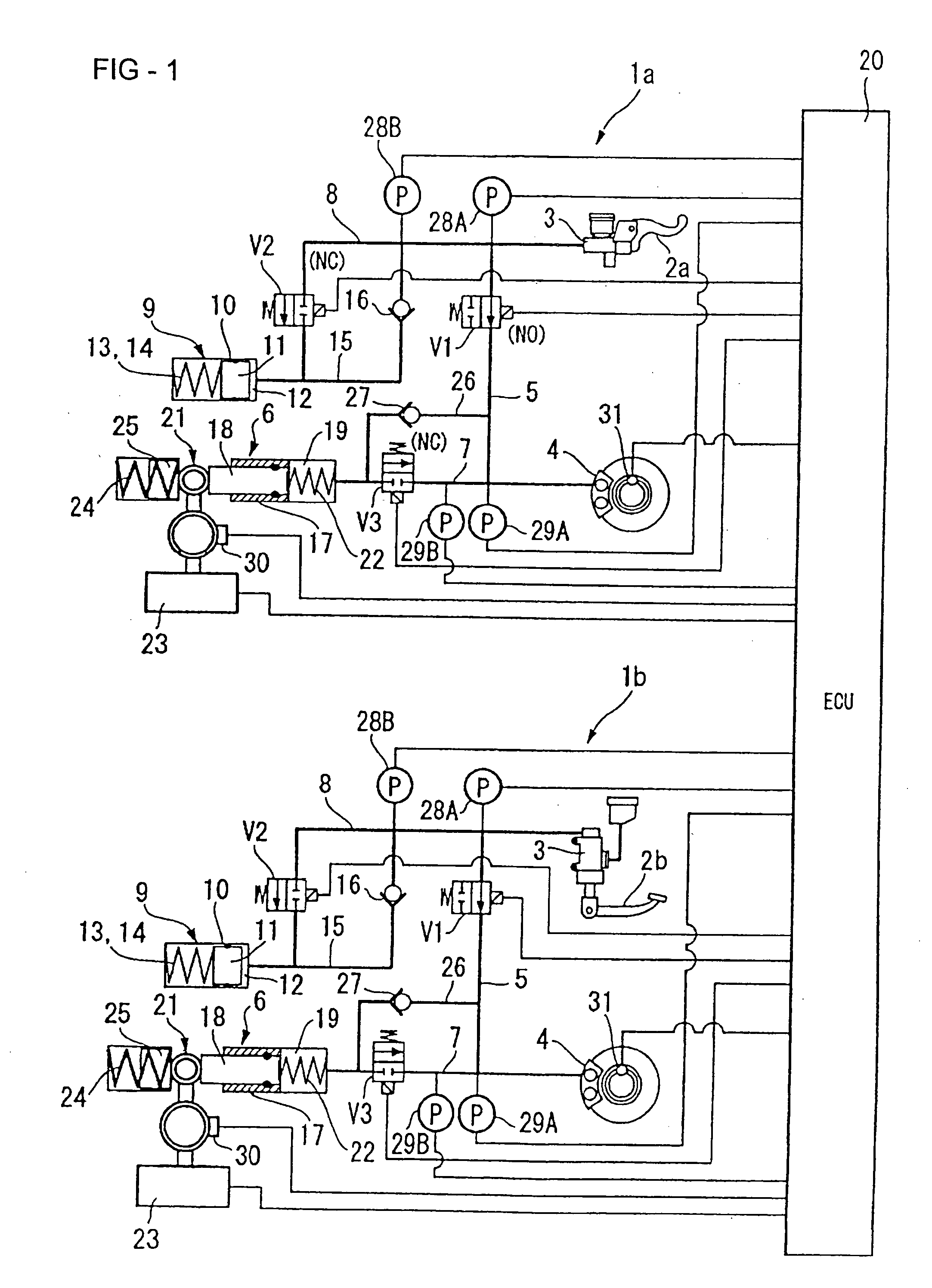
[0035]FIG. 1 is a hydraulic circuit diagram of an electronic braking device for a motorcycle according to the present invention. As shown in the figure, the electronic braking device in this embodiment consists of a front wheel brake circuit 1a and a rear wheel brake circuit 1b which are independent of each other and connected via an electronic control unit (ECU) 20.

[0036] The front wheel brake circuit 1a and the rear wheel brake circuit 1b are substantially structurally the same, except that for brake control, the front wheel brake circuit 1a relies on a brake lever 2a as a brake operating unit 2 and the rear wheel brake circuit 1b relies on a brake pedal 2b as a brake operating unit 2. Therefore, only the front wheel brake circuit 1a will be described in detail, and the elements of the rear wheel brake circuit 1b which are the same as those of the front wheel brake circuit 1a are designated by the same reference numerals and their descriptions are omitted.

[0037] The electronic br...

second embodiment

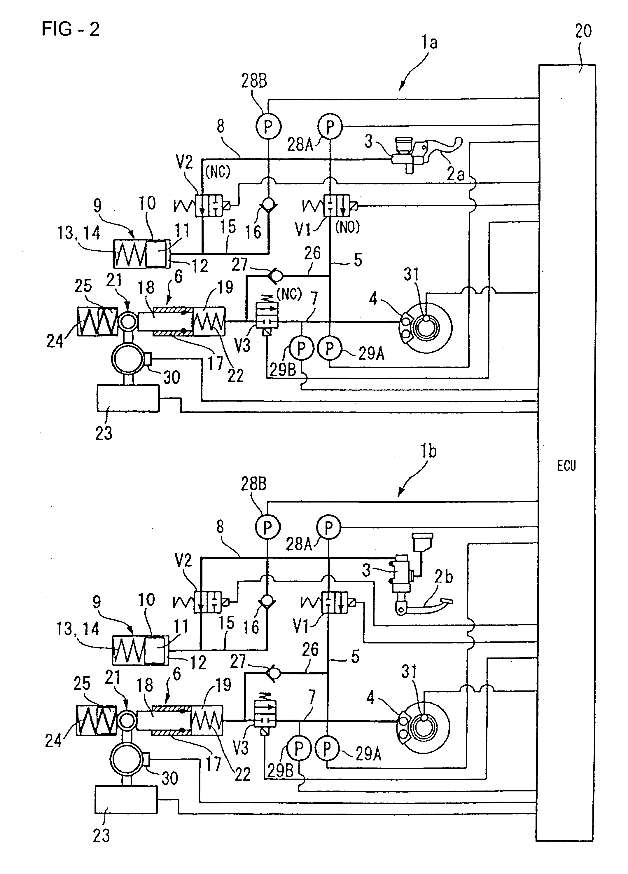
[0090]FIG. 6 is a hydraulic circuit diagram of a braking device for a motorcycle according to the present invention. As shown in the figure, the braking device in this embodiment consists of a front wheel brake circuit 1a and a rear wheel brake circuit 1b which are independent from each other and connected via an electronic control unit (ECU) 20.

[0091] As in the first embodiment, the front wheel brake circuit 1a and the rear wheel brake circuit 1b of the second embodiment are structurally substantially the same except that for brake control, the front wheel brake circuit 1a relies on a brake lever 2a as a brake operating unit 2 and the rear wheel brake circuit 1b relies on a brake pedal 2b as a brake operating unit 2. Therefore, only the front wheel brake circuit 1a will be described in detail, and the elements of the rear wheel brake circuit 1b which are the same as those of the front wheel brake circuit 1a are designated by the same reference numerals and their descriptions are om...


PUM


Abstract

An electronic braking device is provided which easily generates a braking force depending on the amount of brake operation in a range in which the amount of brake operation is small, just after the start of brake operation, and which protects a fluid pressure sensor from a fluid pressure beyond its tolerance. The electronic braking device activates a brake caliper through an electronic control unit (ECU) according to a signal in response to a braking request from a driver, and is provided with a first pressure sensor and a second pressure sensor for detecting the requested braking amount. The first pressure sensor and the second pressure sensor are different from each other in detection resolution and detection range. A relief valve unit r is provided which, when a fluid pressure above a prescribed level is applied to the master cylinder 3, relieves this fluid pressure.

Description

CROSS-REFERENCE TO RELATED APPLICATIONS [0001] The present invention claims priority under 35 USC 119 based on Japanese patent applications No. 2004-364966, filed on Dec. 16, 2004 and No. 2005-011361, filed on Jan. 19, 2005. The subject matter of these priority documents is incorporated by reference herein. BACKGROUND OF THE INVENTION [0002] 1. Field of the Invention [0003] The present invention relates to an electronic braking device. In particular, the present invention relates to an electronic braking device for a vehicle such as, for example, for a motorcycle. [0004] 2. Description of the Background Art [0005] A number of different designs for electronic braking devices, also known as by-wire type braking devices, are known. These types of braking devices detect the amount of the driver's brake operation, such as the pressure applied to a brake lever, and electrically perform braking according to the detection result. In this type of electronic braking device, the amount of brak...

Claims


Application Information

Patent Timeline
IPC IPC(8): B60T8/88
CPCB60T7/042B60T8/1706B60T8/3225B60T8/885B60T2270/404B60T2270/413B60T2270/82
Inventor NAKAYAMA, MASANOBUTAKENOUCHI, KAZUYATAKAHASHI, HIDEOOGAWA, SUMITAKATANI, KAZUHIKONISHIKAWA, YUTAKA
Owner HONDA MOTOR CO LTD
Why Eureka
Try Eureka