Braking system and automatic brake actuator

a technology of automatic brake actuator and braking system, which is applied in the direction of braking system, rotary clutch, fluid coupling, etc., can solve the problems of difficulty in generating hydraulic pumps in the abs and/or in the vsa system, noise and vibration, and precision, and achieve the effect of improving the braking feeling

Inactive Publication Date: 2009-08-13
HONDA MOTOR CO LTD
View PDF6 Cites 17 Cited by
  • Summary
  • Abstract
  • Description
  • Claims
  • Application Information

AI Technical Summary

Benefits of technology

[0010]The present invention has been made in view of the above-described circumstances. An object of the present invention is to provide a braking system which can achieve precise control of brake-fluid pressure for automatic braking control that is independent of the braking action of the driver, as well as to give the driver an enhanced braking feeling when the driver depresses a brake pedal during the automatic braking control.
[0012]With the configuration described above, the actuator, including the slave cylinder and the electric motor, is disposed between the master cylinder and the wheel cylinders, and generates brake-fluid pressure by the forward motion of the piston that is driven by the driving power of the electric motor. The actuator is activated by the electric signal independent of a braking action of the driver. In addition, the electric motor of the actuator is activated only when the wheel cylinders are controlled to brake their respective wheels are automatically. Accordingly, the vibration and noise produced in the case of the above-described configuration can be reduced in comparison with a case where the brake-fluid pressure to activate the wheel cylinders is generated by driving a hydraulic pump. In addition, the actuator is activated only when the wheel cylinders are to be automatically activated. Accordingly, simultaneous occurrence of the operation of the slave cylinder and the braking action of the driver becomes less frequent. This reduces the impact of the operation of the actuator on the sensation experienced by the driver at the time of the braking action.
[0018]With the configuration described above, the two parallel systems of fluid passages are provided for connecting the master cylinder and the wheel cylinders. Accordingly, if one of the two systems was to fail for any reason, the other system can provide the back-up for the failed one. In addition because only one slave cylinder is used to provide brake-fluid pressure to the two fluid passage systems, this reduces the number of the component parts.
[0020]With the configuration described above, the slave cylinder is activated during the operation of the congestion follow-up travel control that makes the subject vehicle automatically start and stop in response to the start and the stop of the preceding vehicle. Accordingly, frequent braking actions of the driver are no longer necessary during the congestion follow-up travel control, so that the number of actions required to be performed by the driver can be reduced.
[0022]With the configuration described above, the electric motor generates brake-fluid pressure by driving forward the piston which is slidably fitted into a cylinder main body. The electric motor is activated to provide brake-fluid pressure only when the wheel cylinders are to be automatically activated without relying on any braking actions by the driver. Accordingly, braking force can be generated even without the driver applying any force to the brake pedal. In addition, the brake-fluid pressure is generated by making the electric motor drive the piston of the slave cylinder, so that the vibrations and noise can be reduced in comparison with a case where a hydraulic pump is driven to generate brake-fluid pressure. Moreover, the automatic braking actuator is activated only when the wheel cylinder is to be automatically activated by the brake-fluid pressure from the actuator. Accordingly, the simultaneous occurrence of the operation of the automatic braking actuator and the braking actions of the driver becomes less frequent. This can reduce an impact of the operation of the automatic braking actuator on the sensation experienced by the driver at the time of the braking action.
[0024]With the configuration described above, the electric motor is activated during the congestion follow-up travel control that makes the subject vehicle automatically start and stop in response to the start and the stop of the preceding vehicle. Accordingly, frequent braking actions of the driver are no longer necessary during the congestion follow-up travel control, so that the number of actions required to be performed by the driver can be reduced.

Problems solved by technology

In the former case, when the driver depresses the brake pedal while the electronically-controlled vacuum booster is in operation this brings about the following problem.
The hydraulic pumps provided in the ABS and / or in the VSA system have difficulty in generating, with precision, the low brake-fluid pressure needed for the congestion follow-up travel control.
In addition, the hydraulic pumps in operation cause noise and vibrations.

Method used


Image

  • Braking system and automatic brake actuator
  • Braking system and automatic brake actuator
  • Braking system and automatic brake actuator

Examples


Embodiment Construction

[0031]An exemplary embodiment of the present invention will be described below with reference to FIGS. 1 to 3.

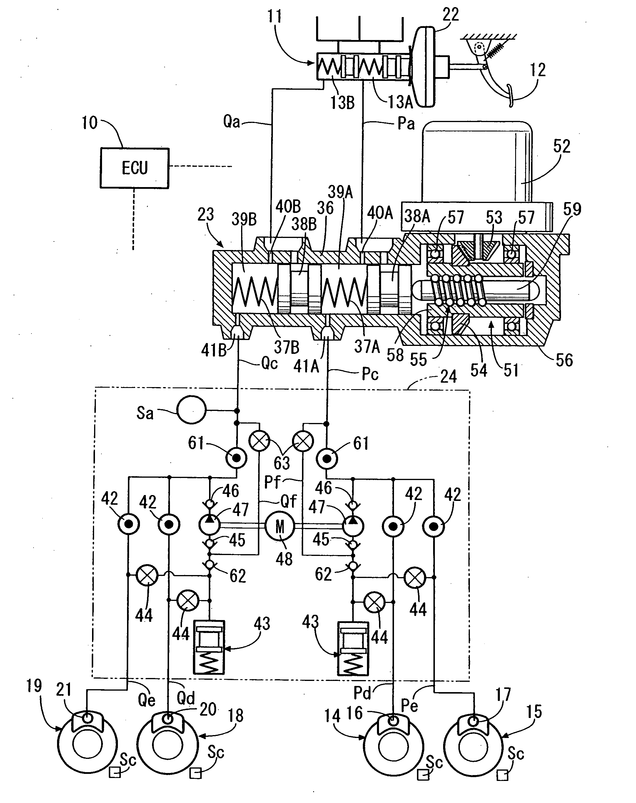
[0032]As shown in FIG. 1, a tandem-type master cylinder 11 is provided with a vacuum booster 22. The master cylinder 11 includes first hydraulic chambers 13A and 13B that output brake-fluid pressure in accordance with the pedal force generated when a driver depresses a brake pedal 12. The first hydraulic chamber 13A is connected, for example, to a wheel cylinder 16 of a disc-brake apparatus 14 of the left-hand-side front wheel via fluid passages Pa, Pc, and Pd. In addition, the first hydraulic chamber 13A is connected, for example, to a wheel cylinder 17 of a disc-brake apparatus 15 of the right-hand-side rear wheel via fluid passages Pa, Pc, and Pe. The other first hydraulic chamber 13B is connected, for example, to a wheel cylinder 20 of a disc-brake apparatus 18 of the right-hand-side front wheel via fluid passages Qa, Qc, and Qd. In addition, the first hydraulic chamber ...


PUM


Abstract

A braking system comprising wheel cylinders that brake respective wheels when brake-fluid pressure is applied to the wheel cylinders, a master cylinder that generates brake-fluid pressure in response to a braking action of a driver, and an actuator including a slave cylinder and an electric motor, which is disposed between the master cylinder and the wheel cylinders, and which generates brake-fluid pressure by a forward motion of a piston driven by a driving power of the electric motor. The actuator is activated by an electric signal independent of a braking action of the driver and the actuator is activated only when the wheel cylinders are to be automatically activated without relying on the braking action of the driver.

Description

CROSS-REFERENCE TO RELATED APPLICATIONS[0001]The present invention claims priority under 35 USC §119 based on Japanese patent application No 2008-30040 filed 12 Feb. 2008. The subject matter of these priority documents is incorporated by reference herein.BACKGROUND OF THE INVENTION[0002]1. Field of the Invention[0003]The present invention relates to a braking system comprising: a master cylinder that generates brake-fluid pressure by an operational force caused by a braking action of a driver; wheel cylinders that brake respective wheels; and a slave cylinder which is disposed between the master cylinder and the wheel cylinders, and which generates brake-fluid pressure by a forward motion of a piston driven by a driving power of an electric motor activated by an electric signal according to a braking action of the driver. The present invention also relates to an automatic-braking actuator which carries out a braking control by supplying brake-fluid pressure to wheel cylinders that b...

Claims


Application Information

Patent Timeline
Patent Type & Authority Applications(United States)
IPC IPC(8): F15B7/00
CPCB60T8/489B60T13/745B60T13/686
Inventor HATANO, KUNIMICHI
Owner HONDA MOTOR CO LTD
Why Eureka
Try Eureka