Thrust vector control for hybrid propellants rocket engine with embedded fluid injection ports

a technology of hybrid propellant and fluid injection port, which is applied in the field of hybrid propellant rocket engine configuration, can solve the problems of low volumetric loading, solid-fuel regression rate, and standard hybrid rocket engine that has not yet found commercial spaceflight applications

Pending Publication Date: 2020-07-30
LAB REACTION DYNAMICS INC
View PDF0 Cites 2 Cited by
  • Summary
  • Abstract
  • Description
  • Claims
  • Application Information

AI Technical Summary

Problems solved by technology

Standard hybrid rocket engines have not yet found commercial spaceflight applications because they suffer from slow solid-fuel regression rates, low volumetric loading and relatively poor combustion efficiency, compared to existing alternatives.
This may be due to their inability to burn at a constant oxidizer to fuel ratio, which may result in poor average combustion performance.
This oxidizer to fuel ratio shift throughout the duration of the burn, meaning that the rocket engine's specific impulse cannot be maintained at its peak value, since the fuel is not burning at its optimal stoichiometric ratio.
Turbo-pumps increase complexity since they require gas-generators which incorporate their own injector set, regulators and so on.
Propulsion systems using pressure-fed cycles have practical limits on propellant pressure, which in turn limits combustion chamber pressure, thus minimizing performance.
High pressure propellant tanks require thicker walls and stronger alloys which makes the vehicle tanks heavier, reducing performance and payload capacity.
Additionally, the complexity of the system is largely determined by the type of power cycle used for the rocket propulsion system.
As a result, the high volumetric specific impulse solid polymer fuels may drastically reduce the mechanical complexity of the propulsion systems, which is an inherent problem for any orbital vehicle.
The disclosed rocket engine might drastically reduce the mechanical complexity of propulsion systems, which is an inherent problem for any orbital vehicle.

Method used


Image

  • Thrust vector control for hybrid propellants rocket engine with embedded fluid injection ports
  • Thrust vector control for hybrid propellants rocket engine with embedded fluid injection ports
  • Thrust vector control for hybrid propellants rocket engine with embedded fluid injection ports

Examples


Embodiment Construction

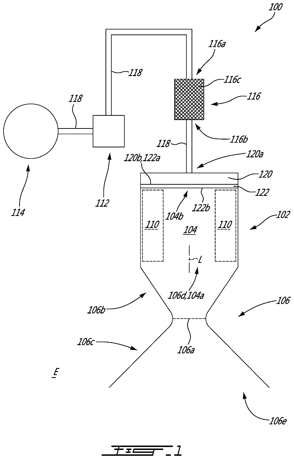
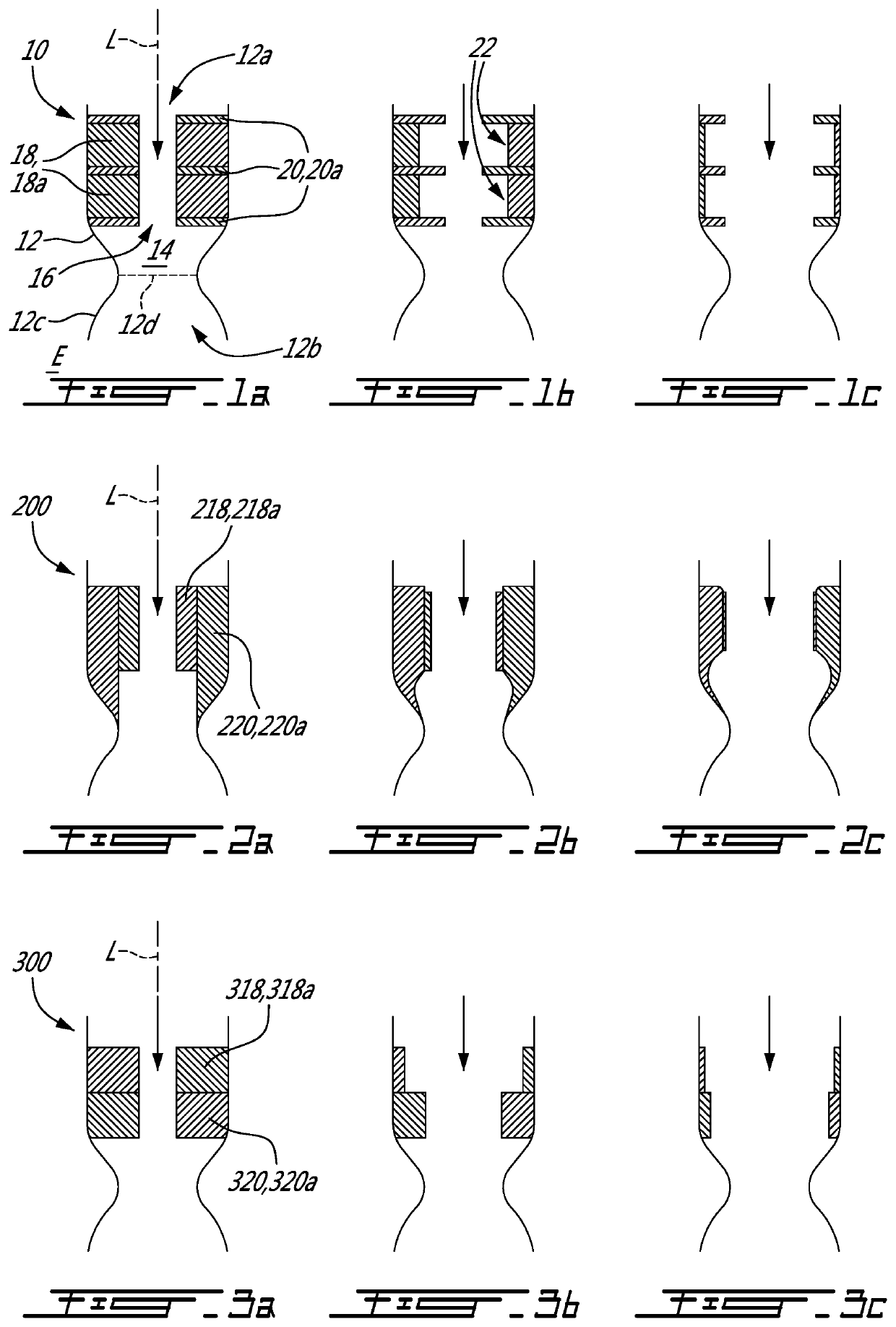
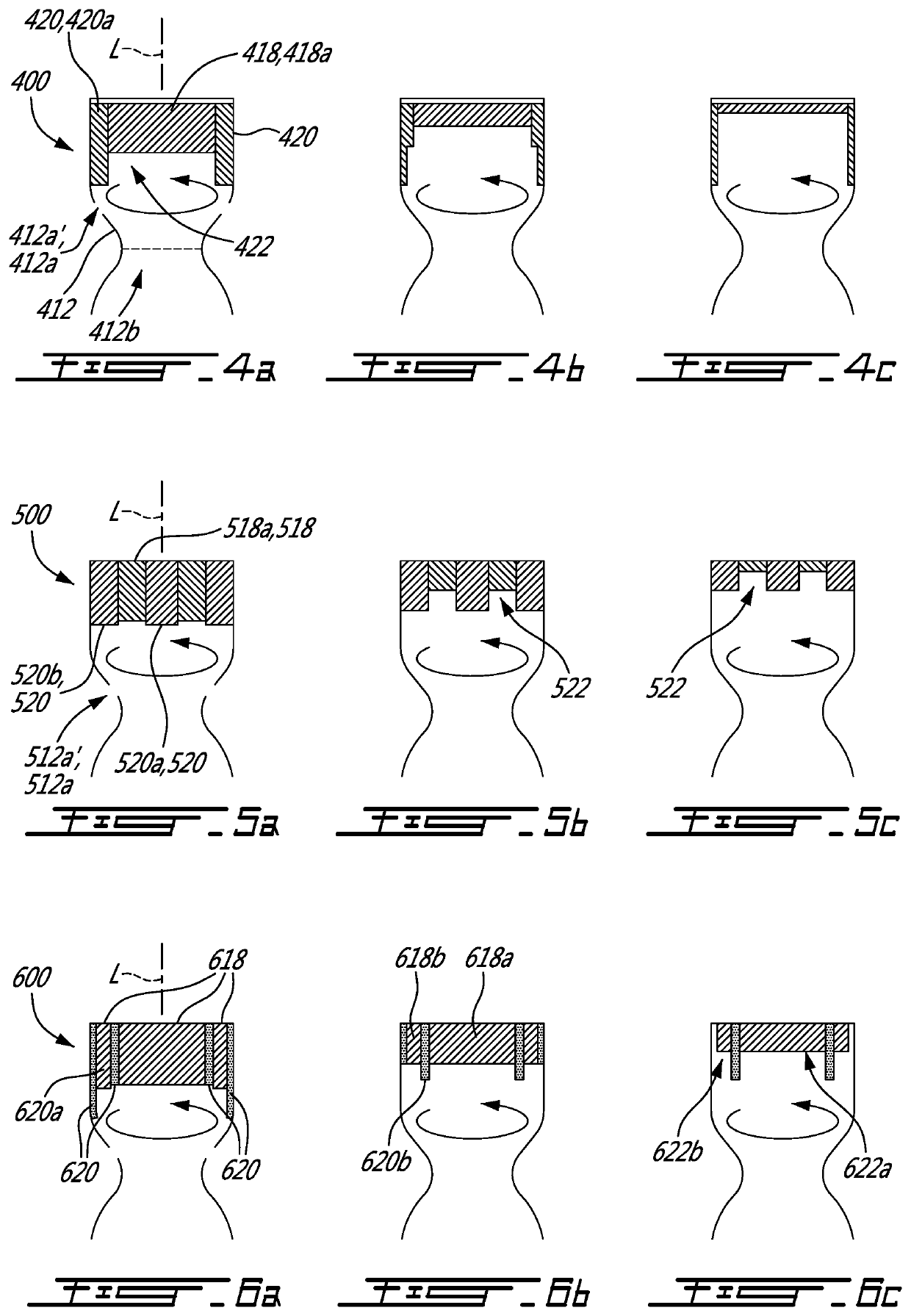
[0045]Referring to FIG. 1, a hybrid rocket engine system is shown generally at 100. A hybrid rocket engine combines a solid propellant as fuel and a liquid oxidizer, hence the “hybrid” terminology. The rocket engine system 100 includes a rocket engine 102 defining a combustion chamber 104 and a convergent-divergent nozzle 106 fluidly connected with the combustion chamber 104 and in which combustion gases generated in the combustion chamber 104 may be accelerated from a subsonic speed to a supersonic speed.

[0046]The nozzle 106 may define a throat 106a at which a speed of the combustion gases is sonic. The nozzle 106 defines a converging section 106b upstream of the throat 106a and a diverging section 106c downstream of the throat 106a. The nozzle 106 has an inlet 106d fluidly connected to an outlet 104a of the combustion chamber 104 and an outlet 106e in fluid communication with an environment E outside the combustion chamber 104. A cross-sectional area of the nozzle 106 taken on a p...


PUM

PropertyMeasurementUnit
temperaturesaaaaaaaaaa
mass ratioaaaaaaaaaa
angle A1aaaaaaaaaa

Abstract

A hybrid rocket engine system has: an oxidizer tank containing a liquid oxidizer; a rocket engine having a combustion chamber operatively connected to the oxidizer tank; a solid propellant fuel within the combustion chamber; a nozzle fluidly connected to the combustion chamber, the nozzle having a convergent section and a divergent section downstream of the convergent section; and a thrust vector control device operatively connected to the divergent section of the nozzle and operable to inject a fluid through at least one aperture defined through the divergent section for controlling a direction of a thrust generated by the rocket engine.

Description

CROSS-REFERENCE TO RELATED APPLICATIONS[0001]This application claims priority from U.S. provisional application No. 62 / 798,679 filed Jan. 30, 2019, the entire contents of which are incorporated by reference herein.TECHNICAL FIELD[0002]The application relates generally to rocket engines and, more particularly, to hybrid propellant rocket engine configurations.BACKGROUND OF THE ART[0003]The development of new high-performance fuel / oxidizer combinations for rocket propulsion applications must take into consideration several important parameters such as the propellants specific impulse, storability, ignition delay, stability and toxicity. Hybrid rocket propellants have the potential to address some of the drawbacks of liquid alternatives, mainly because of their relative simplicity, low development cost, the ability to control their thrust and re-ignite them following partial burns, and because it may alleviate the requirement to match the momenta of the dual propellant streams during t...

Claims


Application Information

Patent Timeline
Patent Type & Authority Applications(United States)
IPC IPC(8): F02K9/82F02K9/08
CPCF05D2230/30F02K9/82F05D2300/11F05D2300/132F05D2300/177F02K9/08F02K9/72F02K9/28F02K9/32B64G1/404F02K9/10F02K9/97F02K9/972F02K9/52F02K9/62
Inventor ELZEIN, BACHARGAGNON, MIGUELGOULET-BOURDON, MAXIME
Owner LAB REACTION DYNAMICS INC
Why Eureka
Try Eureka