Pressure-driven flow rate control valves

Active Publication Date: 2021-05-13
BECTON DICKINSON & CO
View PDF0 Cites 0 Cited by
  • Summary
  • Abstract
  • Description
  • Claims
  • Application Information

AI Technical Summary

Benefits of technology

The patent text describes a device that can control the size of an opening, which can affect the flow of fluid through the device. This allows for the device to be used in different configurations, with each configuration having a different size of the opening. This feature can prevent fluid from flowing through the device in certain configurations. Overall, this technology provides a way to control the flow of fluids in a variety of situations.

Problems solved by technology

Failure to do so may compromise the quality of the fluid.
In instances where the fluid is required for medical treatment or diagnostics, failure to maintain a safe flow rate could result in misdiagnosis, lost time and resources, delayed treatment, serious injury, and potentially death.
In some instances, vacuum containers are incompatible for use with intravenous catheter lines.
For example, a vacuum pressure of a vacuum container may draw the blood sample through the intravenous catheter at a flow rate that damages the live blood cells.
Alternatively, a vacuum pressure may be insufficient for a particular intravenous catheter, whereby the fill time is unnecessarily prolonged.
While use of a syringe enhances control opportunities over the draw, sample quality may suffer if a clinician introduces a significant vacuum to reduce fill time.
Thus, while systems and methods currently exist for collecting or dispensing fluids at a desired flow rate, challenges still exist.

Method used


Image

  • Pressure-driven flow rate control valves
  • Pressure-driven flow rate control valves
  • Pressure-driven flow rate control valves

Examples


Embodiment Construction

[0041]The presently preferred embodiments of the present invention will be best understood by reference to the drawings, wherein like reference numbers indicate identical or functionally similar elements. It will be readily understood that the components of the present invention, as generally described and illustrated in the figures herein, could be arranged and designed in a wide variety of different configurations. Thus, the following more detailed description, as represented in the figures, is not intended to limit the scope of the invention as claimed, but is merely representative of presently preferred embodiments of the invention.

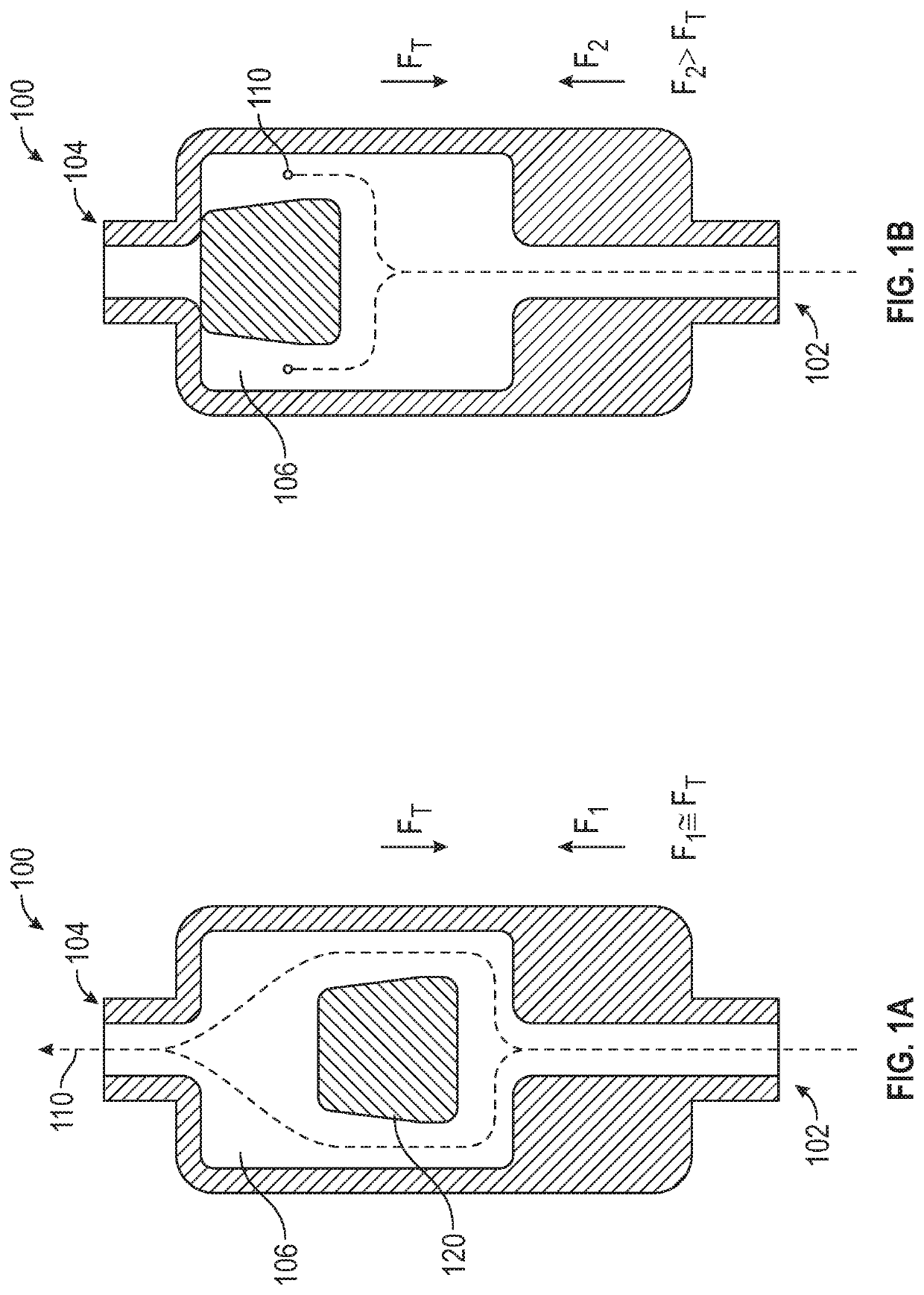
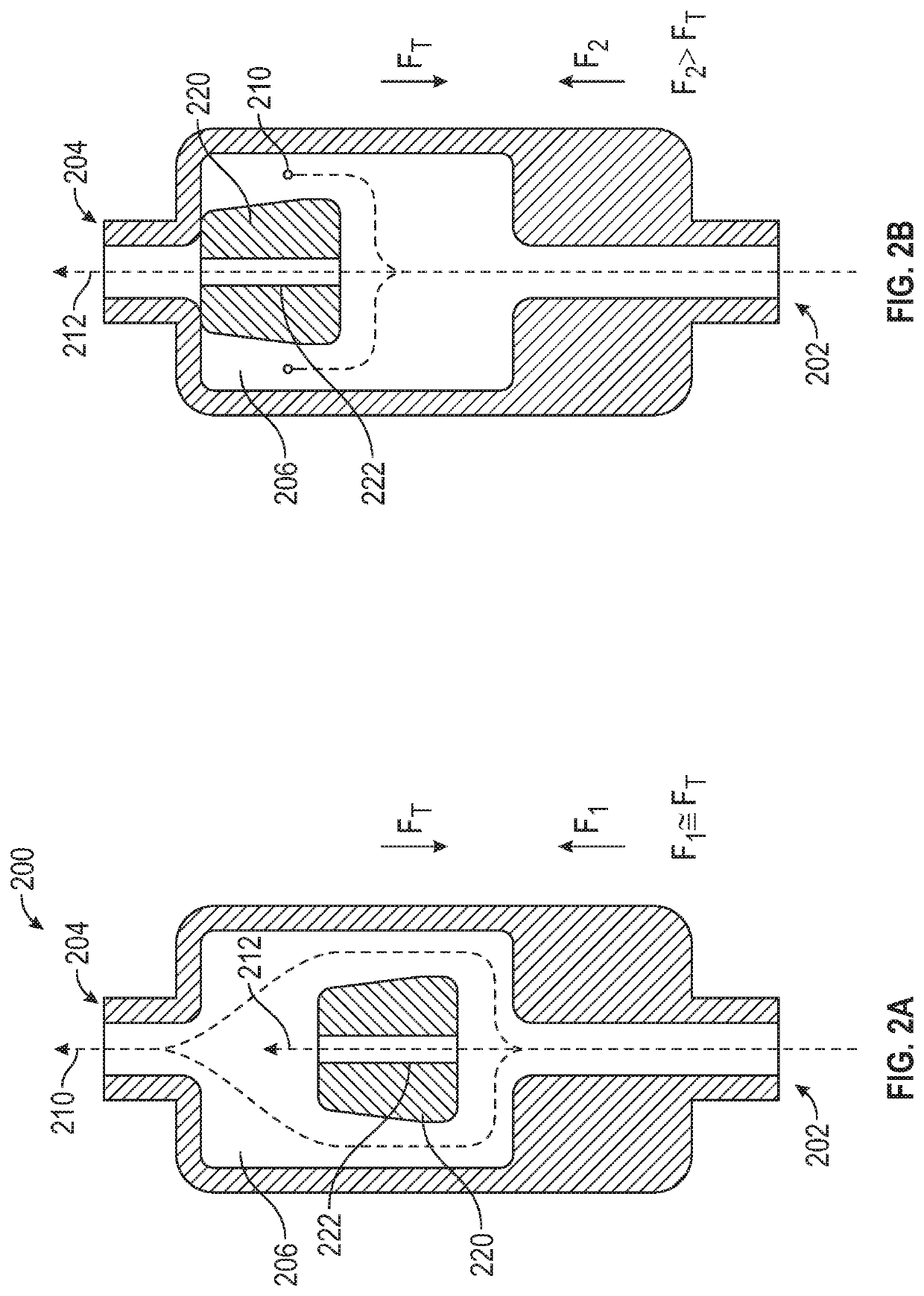
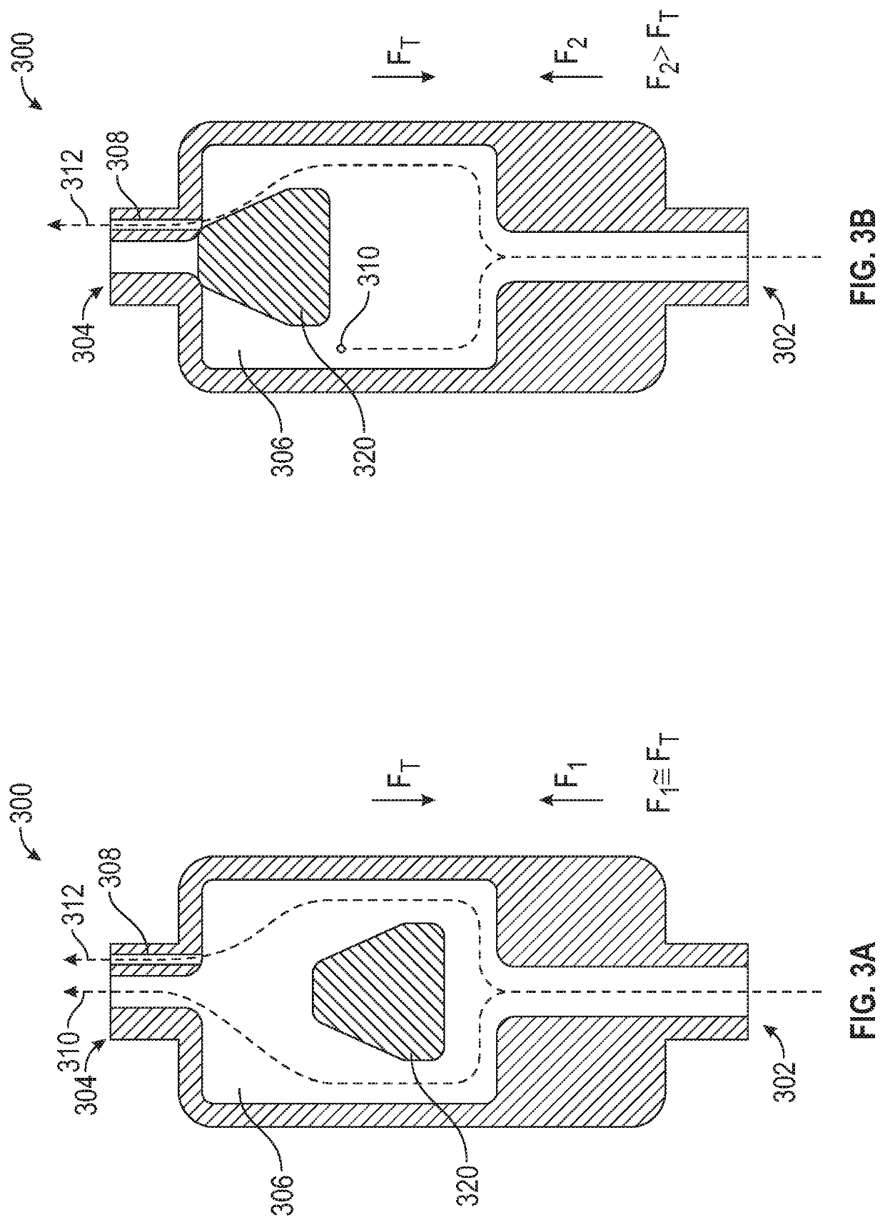
[0042]Referring now to FIG. 1, a valve 100 for controlling the flow of a fluid is shown. Valve 100 generally comprises an enclosure having an inlet 102, an outlet 104, and an interior 106 interposed therebetween. Valve 100 may comprise any structural form, shape, dimension, or size as may be desired. In some embodiments, valve 100 comprises an in-line...


PUM


Abstract

A storage container having a base storage compartment configured to receive a divider by which the storage compartment is divided into two or more sub-compartments, wherein divider includes a tool configured to provide a secondary utility or function unrelated to dividing the storage compartment.

Description

RELATED APPLICATIONS[0001]This application claims the benefit of U.S. Provisional Application No. 62 / 934,956, filed Nov. 13, 2019, and entitled PRESSURE-DRIVEN FLOW RATE CONTROL VALVES, which is incorporated herein in its entirety.FIELD OF THE INVENTION[0002]This invention generally relates to valves for use in systems configured to collect or dispense fluids at a desired flow rate. In particular, this invention relates to control valves comprising various components configured to maintain a desired flow rate, and / or prevent the occurrence of an undesirable flow rate. Control valves of the present invention may be incorporated into a variety of devices for use with fluids that are sensitive to flow rates, such as biological liquids comprising live cells, shear-sensitive fluids, emulsions, and chemically unstable fluids.BACKGROUND OF THE INVENTION[0003]There are many instances where it is desirable to transfer a fluid that is sensitive to flow rate. In these instances it is imperativ...

Claims


Application Information

Patent Timeline
IPC IPC(8): F16K15/02F16K15/03F16K15/16
CPCF16K15/021F16K15/026F16K15/16F16K15/03A61B5/15003A61B5/150221A61B5/150946A61B5/150992A61B5/154A61M39/22F16K1/36F16K1/38A61M39/24A61M2039/2413A61M2039/244A61M2039/2473F16K17/34F16K17/28F16K17/30G05D7/0133G05D7/012
Inventor SPATARO, JOSEPHBLANCHARD, CURTIS H.SCHERICH, MEGANHARDING, WESTON F.BURKHOLZ, JONATHAN KARLWANG, BIN
Owner BECTON DICKINSON & CO
Why Eureka
Try Eureka