Injection valve

An injection valve and fluid injection technology, which is applied in the direction of fuel injection devices, special fuel injection devices, charging systems, etc., can solve the problems of reducing rebound, injection valve degradation, etc., and achieve the effect of ensuring manufacturing, ensuring simplicity and cost effectiveness

Inactive Publication Date: 2013-06-12
CONTINENTAL AUTOMOTIVE GMBH
View PDF1 Cites 0 Cited by
  • Summary
  • Abstract
  • Description
  • Claims
  • Application Information

AI Technical Summary

Problems solved by technology

During undesired reopening and closing phases, undesired fluid is dispensed from the injection valve, resulting in degraded performance of the injection valve
Thus, a flow restrictor is provided in the armature of the valve needle to restrict fluid flow towards the upstream end of the armature, thereby causing reduced rebound of the valve needle

Method used


Image

  • Injection valve
  • Injection valve

Examples


Embodiment Construction

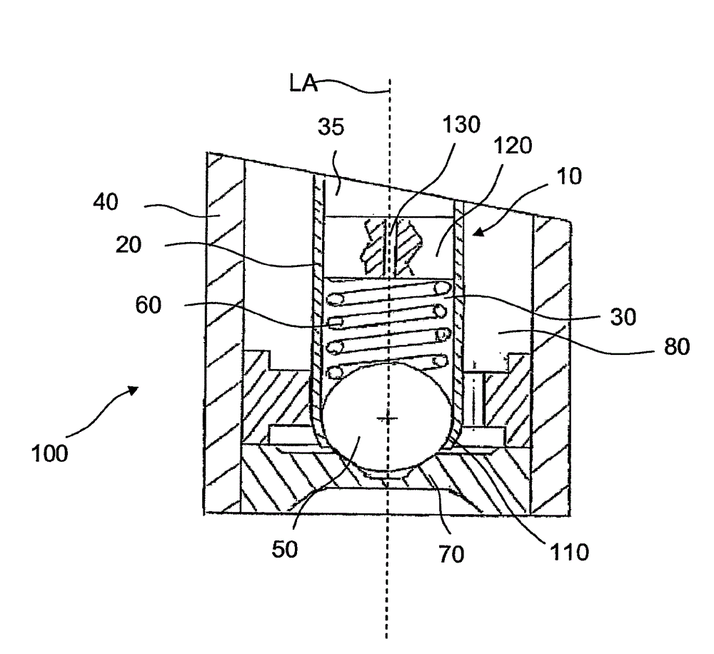
[0024] Injection valve 100 especially suitable for dosing fluid into an internal combustion engine ( figure 1 ) includes an injection valve housing 40 with a central longitudinal axis LA, an injection valve chamber 80 , a valve needle 10 and a valve needle seat 70 . The valve needle 10 comprises a valve needle body 20 , a partition element 120 , a sealing element 50 and a spring element 60 .

[0025] The needle body 20 preferably has a cylindrical shape and is actuated by an actuator of the injection valve 100 , for example an electromagnetic actuator or a piezoelectric actuator. When actuated, the needle body 20 moves axially within the injection valve chamber 80 . The needle body 20 comprises a needle chamber, wherein a partition element 120 is fixedly arranged dividing the needle chamber into a first fluid volume 30 and a second fluid volume 35 . Injection valve chamber 80 , first fluid volume 30 and second fluid volume 35 are designed to be filled with fluid (eg, fuel). ...


PUM


Abstract

Injection valve (100) for injecting fluid, comprising an injection valve housing (40) with an injection valve cavity (80). The injection valve (100) comprises a valve needle (10) being axially moveable within the injection valve cavity (80). The valve needle (10) comprises a valve needle body (20) with a valve needle cavity and a separation element (120) being fixedly arranged within the valve needle cavity and being adopted to divide the valve needle cavity into a first and second fluid volume (30, 90). The separation element comprises at least one fluid passage (130) with a predetermined passage opening to hydraulically connect the first fluid volume (30) with the second fluid volume (90). The valve needle (10) comprises a sealing element (50) being arranged to predetermine the first fluid volume (30) and preventing a fluid injection in a closing position and permitting the fluid injection in further positions. In addition, the valve needle (10) comprises at least one spring element (60) being preloaded and acting on the sealing element (50) towards a maximum axial expansion of the valve needle (10).

Description

technical field [0001] The invention relates to injection valves for injecting fluids. Background technique [0002] Injection valves are widely used, especially for internal combustion engines, in which they may be arranged for dosing fluid into the intake manifold of the internal combustion engine or directly into the combustion chambers of the cylinders of the internal combustion engine. [0003] Injection valves are manufactured in various forms to meet the various needs of various internal combustion engines. Thus, for example, its length, its diameter and the various elements of the injection valve responsible for the way the fluid is metered can vary within wide limits. In addition, the injection valve can accommodate an actuator for actuating a valve needle of the injection valve, for example, the actuator can be an electromagnetic actuator. [0004] In order to enhance the combustion process with regard to the generation of unwanted emissions, corresponding inject...

Claims


Application Information

Patent Timeline
Patent Type & Authority Patents(China)
IPC IPC(8): F02M61/20
CPCF02M2200/306F02M51/066F02M2200/28F02M2200/304F02M61/205F02M61/20F02M51/0685F02M2200/16
Inventor A.阿格雷斯塔G.菲舍蒂L.加尔朱洛M.梅奇
Owner CONTINENTAL AUTOMOTIVE GMBH
Why Eureka
Try Eureka