Automatic spraying machine for steel pipe

An automatic spraying and pipe technology, applied in spray booths, spraying devices, etc., can solve the problems of inability to spray steel pipes, high labor intensity, and unsprayed steel pipes, so as to improve rust prevention ability, improve production efficiency, and reduce production costs. Effect

Active Publication Date: 2020-06-12
上海翎航动力科技有限公司
View PDF7 Cites 16 Cited by
  • Summary
  • Abstract
  • Description
  • Claims
  • Application Information

AI Technical Summary

Problems solved by technology

[0002] Traditional finished steel pipes are usually formed by cold rolling, and the inner and outer walls of cold rolling are generally not sprayed with paint. In construction projects, it takes about 2-3 years from the beginning to the completion. In this way, steel pipes It is easy to rust and rot outdoors in the wind, sun and rain, which greatly shortens the service life of the steel pipe. In order to improve the antirust ability of the steel pipe, the current method is to manually spray the inner and outer walls of the steel pipe. The traditional manual spraying The method is labor-intensive, which brings a large amount of labor to the workers, and it is difficult to manually spray the inner wall of the pipeline.
In addition, due to the long length of the steel pipe, some existing steel pipe spraying equipment on the market cannot spray the entire inner wall of the steel pipe, requiring workers to manually turn around and spray the steel pipe, which brings extra labor to the workers. Moreover, There is no device to drive the steel pipe to rotate, so that the inner wall of the steel pipe is partially unpainted, resulting in the problem of uneven spraying on the inner wall of the steel pipe

Method used


Image

  • Automatic spraying machine for steel pipe
  • Automatic spraying machine for steel pipe
  • Automatic spraying machine for steel pipe

Examples


Embodiment

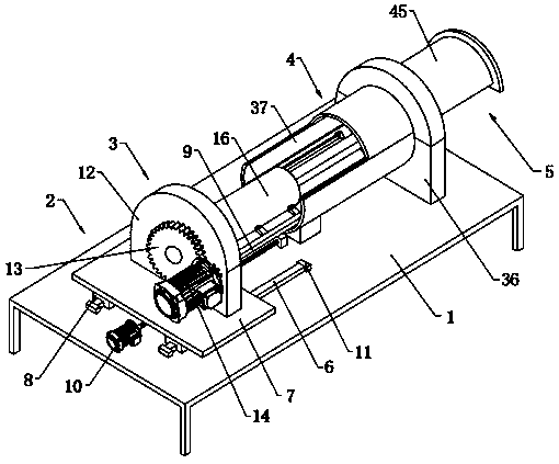
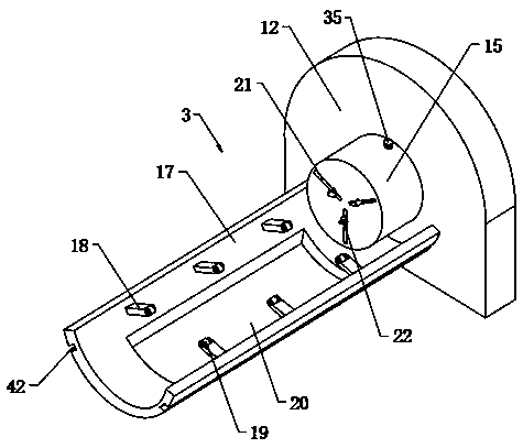
[0025] Embodiment: a kind of automatic spraying machine for steel pipe, constitutes as figure 1 As shown, it includes a workbench 1, and the two ends of the top of the workbench 1 are respectively equipped with a conveying mechanism 2 and an in-pipe spraying mechanism 4. The conveying mechanism 2 transports the steel pipe 16 horizontally to facilitate feeding. The rotating mechanism 3 clamps and rotates the steel pipe 16 to facilitate uniform spraying of the steel pipe 16. An outer spraying mechanism 5 is arranged above the inner spraying mechanism 4, and the inner spraying mechanism 4 and the outer spraying mechanism 5 can spray the steel pipe 16 respectively. The inner and outer walls are sprayed, the clamping and rotating mechanism 3 clamps the steel pipe 16, and the clamping and rotating mechanism 3 is connected with the spraying mechanism 4 in the pipe. The conveying mechanism 2 includes a first slide rail 6 fixed on the top of the workbench, a bearing plate 7 is arranged...


PUM


Abstract

The invention discloses an automatic spraying machine for a steel pipe. The automatic spraying machine comprises a workbench, wherein a conveying mechanism and an in-pipe spraying mechanism are arranged at the two ends of the top of the workbench correspondingly; the conveying mechanism comprises a first sliding rail fixed to the top of the workbench, a bearing plate is arranged above the first sliding rail, and a sliding block matched with the first sliding rail is arranged at the bottom of the bearing plate; a first threaded rod and a first motor are further arranged at the top of the workbench, the bottom of the bearing plate is in threaded connection with the first threaded rod, and the first threaded rod is connected with the output end of the first motor; and a clamping rotating mechanism is arranged above the conveying mechanism, an out-pipe spraying mechanism is arranged above the in-pipe spraying mechanism, the steel pipe is clamped on the clamping rotating mechanism, and theclamping rotating mechanism is connected with the in-pipe spraying mechanism. According to the automatic spraying machine, the overall structure is arranged, so that the inner wall and the outer wallof the steel pipe can be automatically and uniformly sprayed, and the rust prevention capacity of the steel pipe can be improved; and meanwhile, the workload is greatly saved, the production cost is reduced, and the production efficiency is improved.

Description

technical field [0001] The invention relates to a spraying machine, in particular to an automatic spraying machine for steel pipes. Background technique [0002] Traditional finished steel pipes are usually formed by cold rolling, and the inner and outer walls of cold rolling are generally not sprayed with paint. In construction projects, it takes about 2-3 years from the beginning to the completion. In this way, steel pipes It is easy to rust and rot outdoors in the wind, sun and rain, which greatly shortens the service life of the steel pipe. In order to improve the antirust ability of the steel pipe, the current method is to manually spray the inner and outer walls of the steel pipe. The traditional manual spraying The labor intensity of the way is big, brings bigger labor load for worker, and it is difficult to carry out spraying operation to the inner wall of pipeline manually. In addition, due to the long length of the steel pipe, some existing steel pipe spraying equ...

Claims


Application Information

Patent Timeline
Patent Type & Authority Applications(China)
IPC IPC(8): B05B13/02B05B13/06B05B16/40
CPCB05B13/0235B05B13/0663B05B16/405
Inventor 袁江凯蔡燕孙浩然
Owner 上海翎航动力科技有限公司
Why Eureka
Try Eureka