
Sealing mechanism for gap between impeller and volute

A technology of sealing mechanism and impeller, which is applied to components, mechanical equipment, machines/engines, etc. of elastic fluid pumping devices, which can solve the problems of increasing pump energy loss, reducing water supply of water pumps, leakage, etc., and achieve volume reduction loss, simplification of installation process, and reduction of secondary flow

Active Publication Date: 2017-02-15
ZHEJIANG TIANDE PUMPS
View PDF8 Cites 0 Cited by
  • Summary
  • Abstract
  • Description
  • Claims
  • Application Information

AI Technical Summary

Problems solved by technology

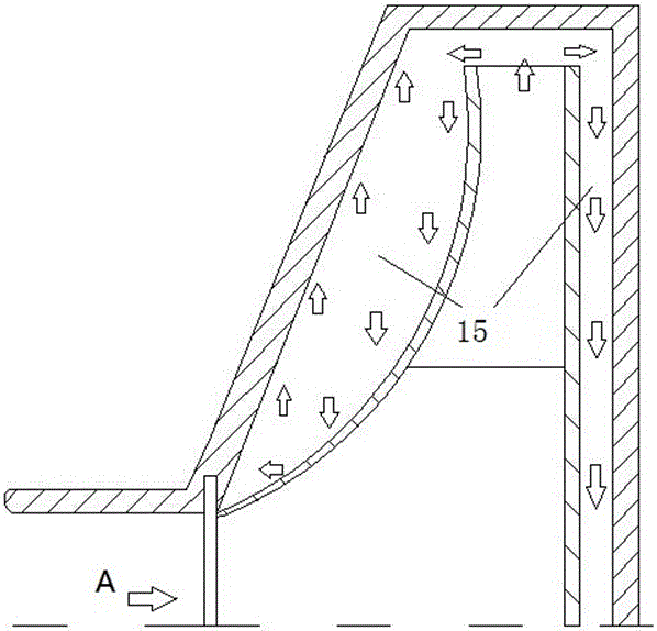
[0002] In the process of converting mechanical energy into liquid energy, the centrifugal pump is accompanied by various losses. These losses can be divided into three types: mechanical loss, volume loss and hydraulic loss. There is a certain gap in the sealing ring at the impeller inlet, so when the pump is working, due to the pressure difference between the impeller outlet and the inlet, part of the high-pressure fluid flowing from the impeller outlet will leak to the impeller inlet through this gap. Energy is obtained in the impeller, but the liquid is not sent out, which reduces the water supply of the pump and increases the energy loss of the pump. This part of the leakage loss caused by the gap is called volume loss

Method used


Image

  • Sealing mechanism for gap between impeller and volute
  • Sealing mechanism for gap between impeller and volute
  • Sealing mechanism for gap between impeller and volute

Examples


Embodiment Construction

[0032] The present invention will be further described below in conjunction with drawings and embodiments.

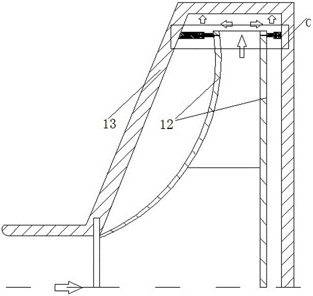
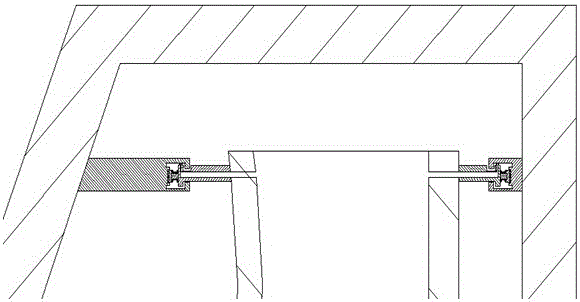
[0033] figure 1 It is a simplified schematic diagram of a pump section in the prior art. The impeller inflow A flows between the cover plate 12 on both sides of the impeller and the inner wall of the volute 13 to form a leakage flow 15 . The present invention as figure 2 and image 3 As shown, the sealing mechanism is installed between the cover plate 12 on both sides of the water outlet of the impeller and the corresponding inner wall of the volute 13, and is installed between the cover plate 12 on both sides of the water outlet of the impeller and the corresponding inner wall of the volute 13. Have the same sealing mechanism, the sealing mechanism includes pressure water ring seal block 2, elastic seal and static ring 1, pressure water ring seal block 2 such as Figure 6 and Figure 7 As shown, the cover plates 12 on both sides are symmetrically opened with a pre...


PUM


Abstract

The invention discloses a sealing mechanism for a gap between an impeller and a volute. The sealing mechanism is installed between cover plates installed at the both sides of the water outlet of the impeller and the inner sidewall of the corresponding volute, and comprises pressure water annular sealing blocks and static rings; the cover plates at the both sides are symmetrically provided with pressure water annular through grooves close to the water outlet of the impeller; one end of each pressure water annular sealing block is connected to one pressure water annular through groove; the other end of each pressure water annular sealing block is installed in an open groove in one end surface of one static ring through an elastic sealing element; the other end surface of each static ring is hermetically fixed on the inner sidewall of the volute. The sealing mechanism is used for realizing sealing for the gap between the impeller and the volute, capable of effectively preventing fluid flowing from the outlet of the impeller to gaps between the front and rear cover plates, and the volute, and greatly reducing capacity losses and the generations of secondary flows and vortexes; meanwhile, with the adoption of the double matching of two types of sealing, the reliability and the error-tolerant rate of the sealing mechanism are improved.

Description

technical field [0001] The invention relates to a sealing mechanism, in particular to a sealing mechanism for the gap between the impeller and the volute. Background technique [0002] In the process of converting mechanical energy into liquid energy, the centrifugal pump is accompanied by various losses. These losses can be divided into three types: mechanical loss, volume loss and hydraulic loss. There is a certain gap in the sealing ring at the impeller inlet, so when the pump is working, due to the pressure difference between the impeller outlet and the inlet, part of the high-pressure fluid flowing from the impeller outlet will leak to the impeller inlet through this gap. Energy is obtained in the impeller, but the liquid is not sent out, which reduces the water supply of the pump and increases the energy loss of the pump. This part of the leakage loss caused by the gap is called volume loss. At the same time, there are such gaps between the back cover plate of the imp...

Claims


Application Information

Patent Timeline
Patent Type & Authority Patents(China)
IPC IPC(8): F04D29/16
CPCF04D29/167
Inventor 崔宝玲饶昆张鑫方晨
Owner ZHEJIANG TIANDE PUMPS
Learn More