Linear electrical connector with helically distributed terminations

Active Publication Date: 2021-08-12
SAFRAN ELECTRICAL COMPONENTS USA INC
View PDF0 Cites 0 Cited by
  • Summary
  • Abstract
  • Description
  • Claims
  • Application Information

AI Technical Summary

Benefits of technology

[0005]Seen in its most essential aspect, the present invention is a pin electrical connector configured to distribute terminated contact diameters helically/radially along a central axis. The connector solves the issue of pin overcrowding

Problems solved by technology

This reduces the effective diameter of the connector and thereby increases the potential density of cont

Method used


Image

  • Linear electrical connector with helically distributed terminations
  • Linear electrical connector with helically distributed terminations
  • Linear electrical connector with helically distributed terminations

Examples


Embodiment Construction

[0034]Reference will now be made in detail to specific embodiments or features, examples of which are illustrated in the accompanying drawings. Generally, corresponding reference numbers will be used throughout the drawings to refer to the same or corresponding parts. Also, wherever possible, the same reference numbers will be used throughout the drawings to refer to the same or the like parts.

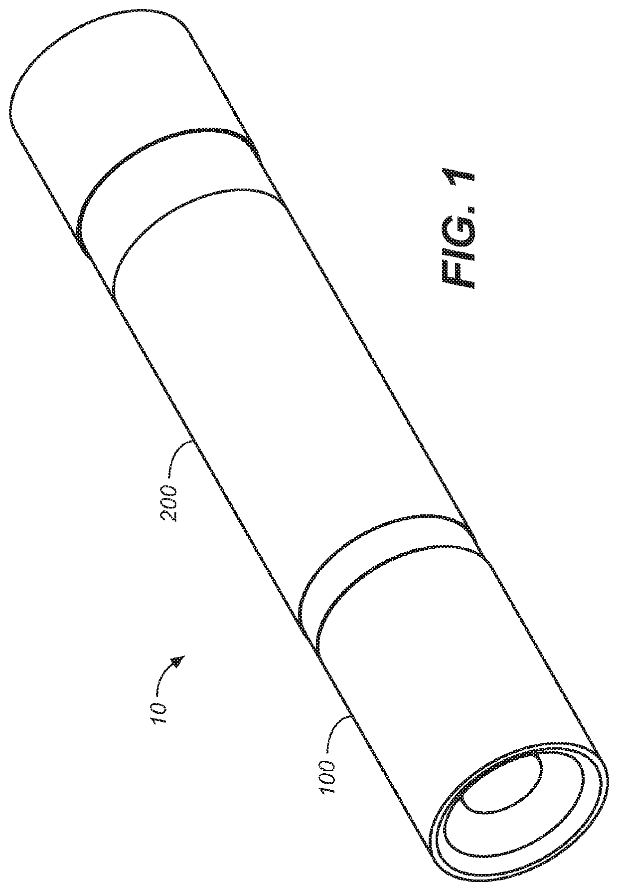
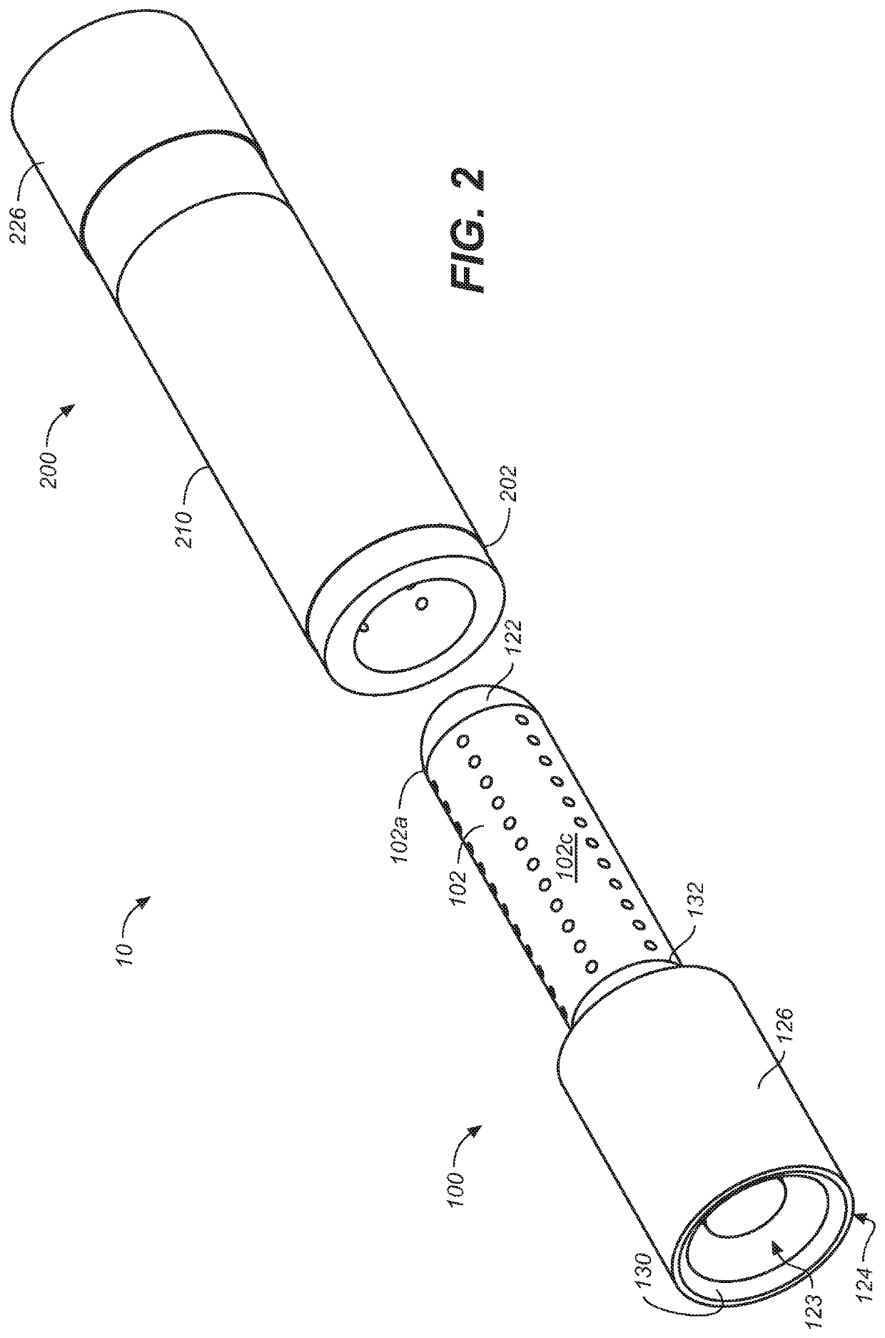
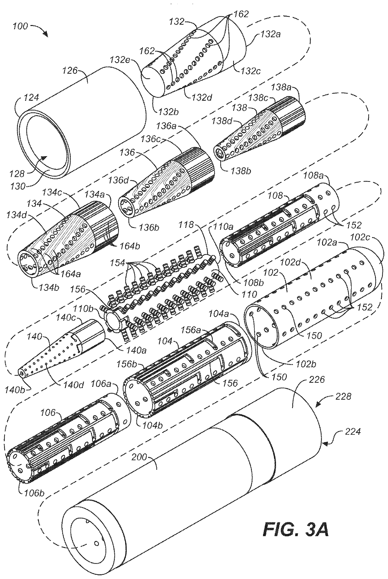
[0035]Referring first to FIGS. 1A through 14, wherein like reference numerals refer to like components in the various views, there is illustrated therein an embodiment of a new and improved electrical connector, generally denominated 10 herein. In an embodiment, the device includes first and second connector matable connectors halves 100, 200, which are a complementary pair comprising a male connector half (a plug) and a female connector half (a receptacle), respectively. As will be immediately appreciated, in an embodiment, the male connector half 100 and the female connector half 200 may be ...


PUM


Abstract

An electrical pin connector including a receptacle and a plug configured for matable connection, the plug and the receptacle each including conical backshells with a surface disposed about a central axis and a plurality of pin receptacles helically disposed in parallel curves around the central axis on the conical backshell surface for terminating conductors.

Description

BACKGROUND OF THE INVENTIONField of the Invention[0001]The present invention relates most generally to electrical conduits, cables, and connectors, and more particularly to a multi-contact electrical connector assembly for interconnect wiring systems, and still more particularly to an electrical connector having plug and receptacle contact terminations configured with terminating pins distributed helically over conical surfaces in both plug and receptacle elements. The inventive connector is adapted for use in highly confined spaces, such as in aircraft electrical connector panels, in which large numbers of electrical cables converge for organization and sorting through harnesses and other cable organization apparatus and for connection to navigation, communication, and electronics systems.Background Discussion[0002]Vehicle and aircraft systems are frequently located remotely from power and signal sources, and conductors and cables frequently pass through structural boundaries, bulk...

Claims


Application Information

Patent Timeline
IPC IPC(8): H01R13/623H01R13/642H01R13/05H01R13/26
CPCH01R13/623H01R13/26H01R13/052H01R13/642H01R13/502
Inventor SEMIK, JARED
Owner SAFRAN ELECTRICAL COMPONENTS USA INC
Why Eureka
Try Eureka