Classifier and a method of modifying a classifier for use with a pulveriser

Inactive Publication Date: 2014-06-05
COAL MILLING PROJECTS (PTY) LTD
View PDF18 Cites 3 Cited by
  • Summary
  • Abstract
  • Description
  • Claims
  • Application Information

AI Technical Summary

Benefits of technology

[0030]an open position in which the adjacent sides of the closure members are no

Problems solved by technology

Known configurations of such classifiers have a drawback in that sometimes foreign objects such as rags, plastic bottles and the like, which are introduced into a pulveriser together with raw material fed into the pulveriser for crushing, find their way into the classifier attached to the pulveriser and in many instances end up blocking or obstructing a rejection outlet of the classifier through which a coarse fraction of the classified particulate material is to be returned to the pulveriser for regrinding.
A problem with this configuration is that the partitions themselves obstruct the flow of material and foreign objects from the openings which leads to blockages.
Obstruction of the reject

Method used


Image

  • Classifier and a method of modifying a classifier for use with a pulveriser
  • Classifier and a method of modifying a classifier for use with a pulveriser
  • Classifier and a method of modifying a classifier for use with a pulveriser

Examples


Example

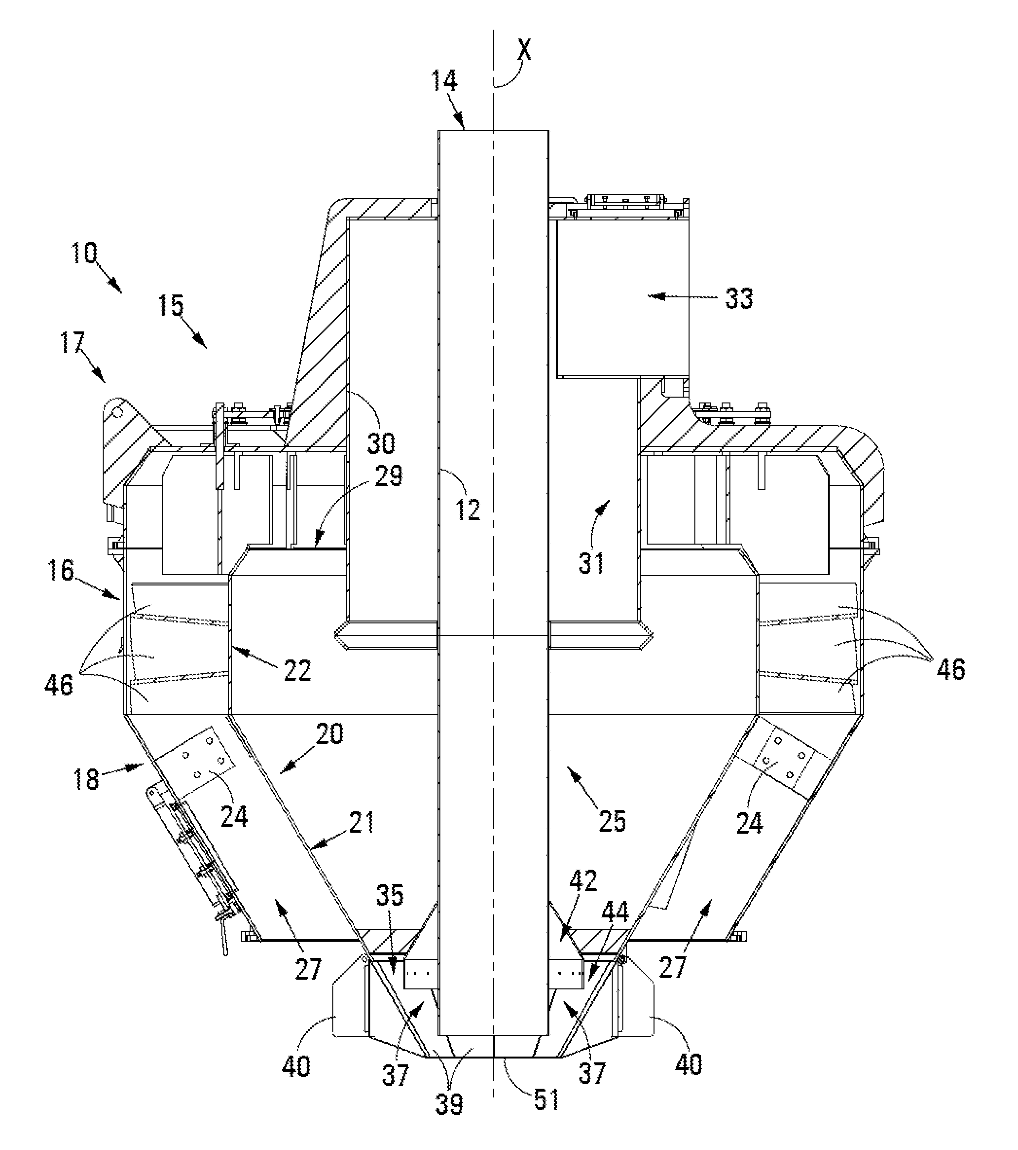
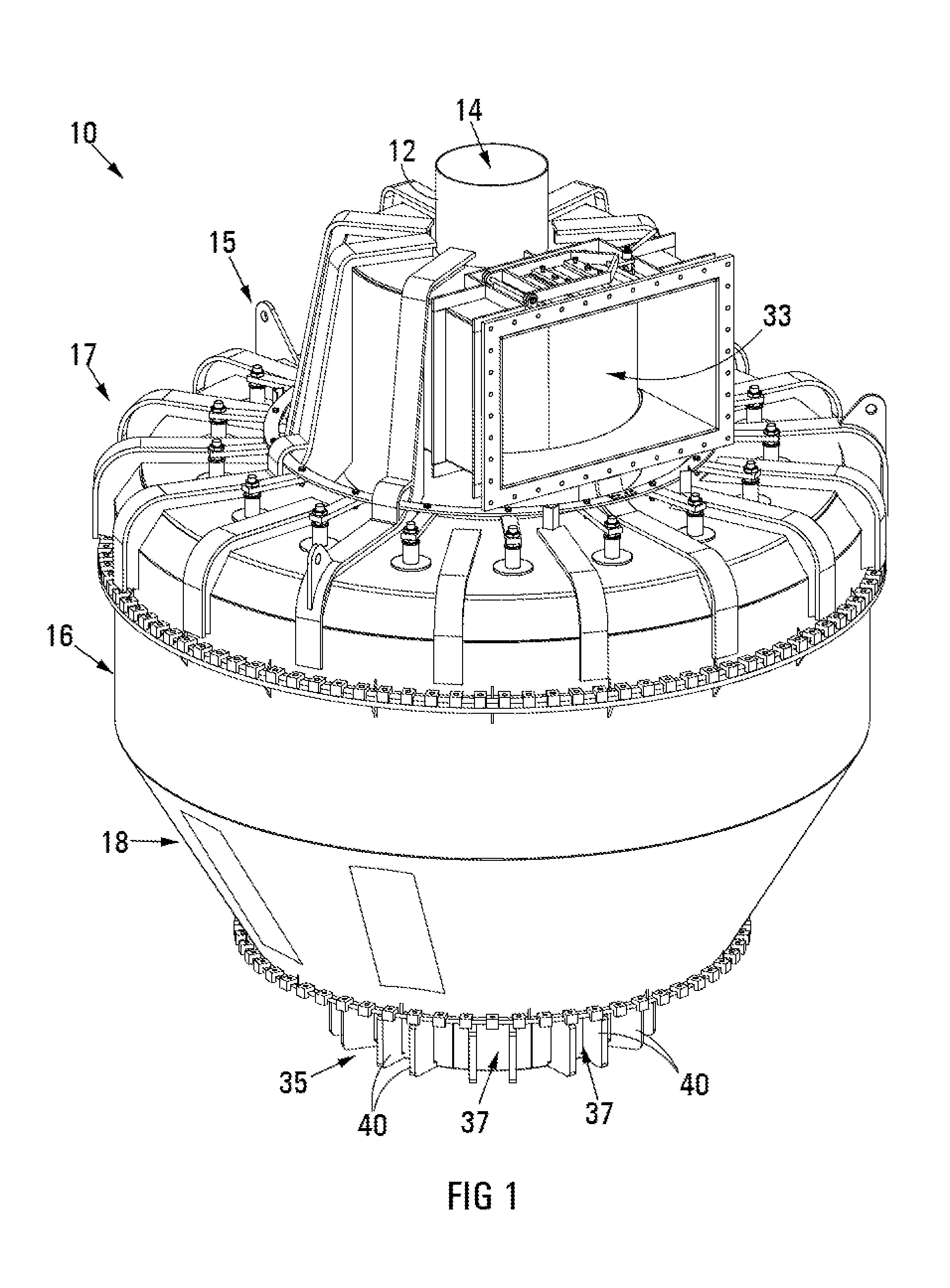
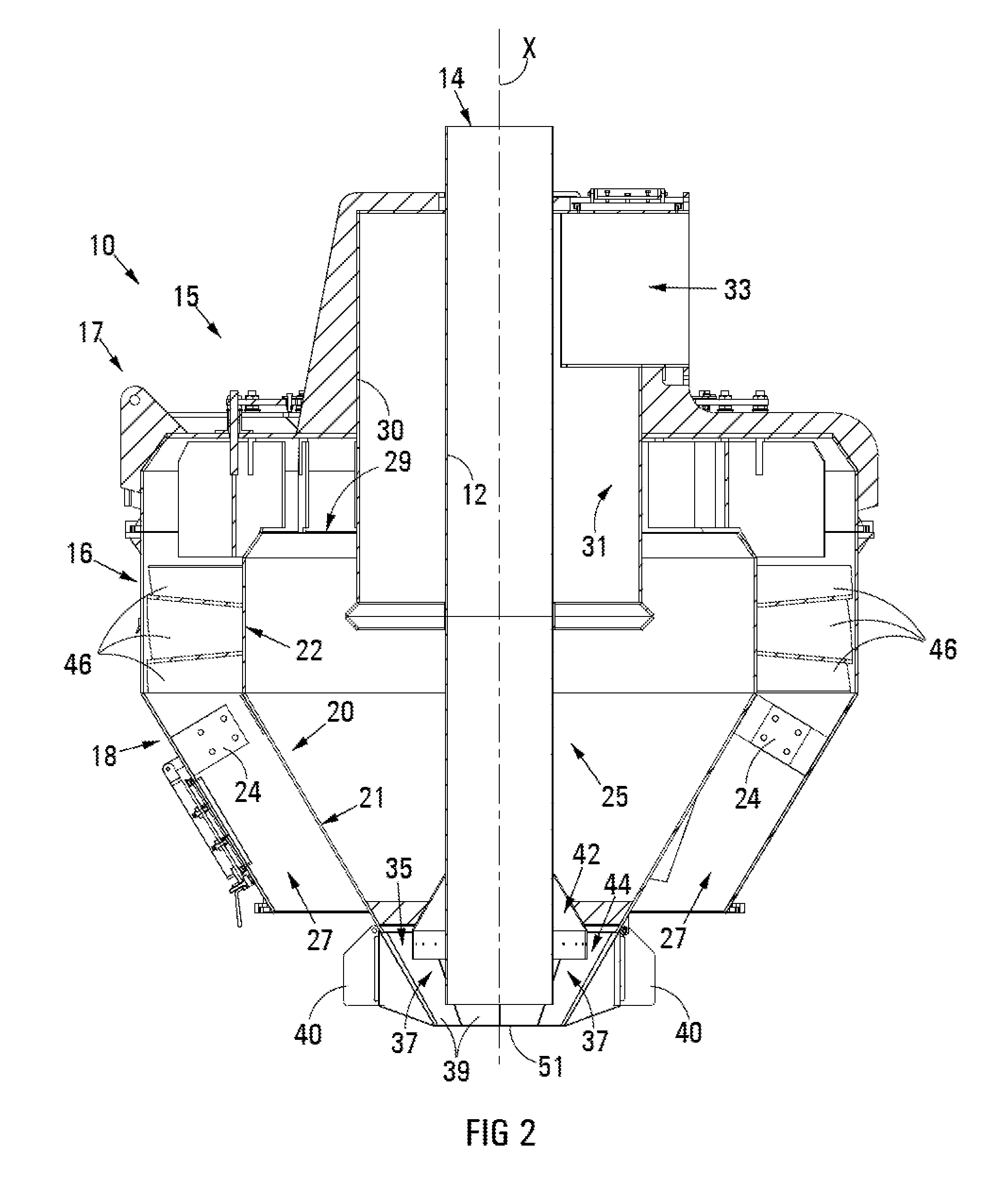
[0046]In FIGS. 1 to 4, reference numeral 10 refers generally to a first embodiment of a classifier in accordance with the invention. The classifier 10 includes a cylindrical feed pipe 12 which extends lengthwise through the middle of the classifier 10 and defines a feed inlet 14 toward an operatively upper end of the pipe 12. Raw material, for example coal, received into the feed pipe 12 via the feed inlet 14 is passed through the classifier 10 along an inlet axis X of the feed pipe 12 to a pulveriser positioned below the classifier 10. In the accompanying drawings the pulveriser is not shown. The classifier 10 further includes an external housing which comprises an upper part 15 and a frusto-conical lower part 18. The upper part 15 comprises a generally cylindrical lower region 16, which is connected to the frusto-conical lower part 18 of the external housing, and a roughly dome-shaped upper region 17.

[0047]The classifier 10 further includes an internal housing 20 (see FIG. 2) whic...

Example

[0054]A second embodiment of a classifier in accordance with the invention is shown in FIG. 6 and is designated by reference numeral 100. The structure and principle of operation of the classifier 100 is essentially the same as the classifier 10 described above and a description of the structure and operation of the classifier 100 will therefore not be repeated here. The configuration of a rejection gate 350 of the classifier 100 varies slightly in comparison to the classifier 10. In FIG. 6 illustrating the classifier 100, the same reference numerals used above to identify features of the classifier 10 have been used to designate similar features of the classifier 100. The rejection gate 350 includes a plurality of closure members 37 which are arranged side-by-side around a lower periphery of the grit funnel 21 in similar fashion as the rejection gate 35. Each closure member 37 includes a generally triangular flap 39 to which weights 40 are attached. In this instance, the flange 420...


PUM

PropertyMeasurementUnit
Weightaaaaaaaaaa
Areaaaaaaaaaaa
Surface areaaaaaaaaaaa

Abstract

The invention relates to a classifier 10 for use with a pulveriser which pulverises raw material. The classifier 10 classifies crushed material into a fine fraction which is expelled via an upper fuel outlet 33 and a coarse fraction which is returned to the pulveriser via a lower rejection outlet 44 for further crushing. The classifier 10 has an internal housing 20 which defines a classification zone 25 and a plurality of triangular flaps 39, each of which are pivotally attached to the housing 20. The flaps 39 are displaceable between a closed position in which they are arranged alongside one another such that sides of adjacent flaps 39 are in abutment and they together define a skirt having a continuous periphery; and an open position in which the flaps 39 are outwardly displaced, widening the outlet 44 in order to allow built-up coarse material to be discharged.

Description

FIELD OF INVENTION[0001]This invention relates generally to pulverisers or mills used to crush or grind raw material such as fossil fuels into fine particles suitable for combustion in steam-generating furnaces of fossil fuel power plants. More particularly, this invention relates to a classifier attached to such a pulveriser for classifying crushed particulate material received from the pulveriser into a sufficiently fine fraction which is suitable for combustion and a coarse fraction which is rejected and returned to the pulveriser.BACKGROUND OF INVENTION[0002]Particle classifiers as identified above are well known in the art and the operation of such classifiers will therefore not be expounded upon in detail below. Known configurations of such classifiers have a drawback in that sometimes foreign objects such as rags, plastic bottles and the like, which are introduced into a pulveriser together with raw material fed into the pulveriser for crushing, find their way into the classi...

Claims


Application Information

Patent Timeline
IPC IPC(8): B02C23/12
CPCB02C23/12B07B7/08Y10T29/49716B04C9/00
Inventor GOOSEN, PIERRE
Owner COAL MILLING PROJECTS (PTY) LTD
Why Eureka
Try Eureka