

Armature for a solenoid actuator
- Summary
- Abstract
- Description
- Claims
- Application Information
AI Technical Summary
Benefits of technology
Problems solved by technology
Method used
Image

Examples
first embodiment
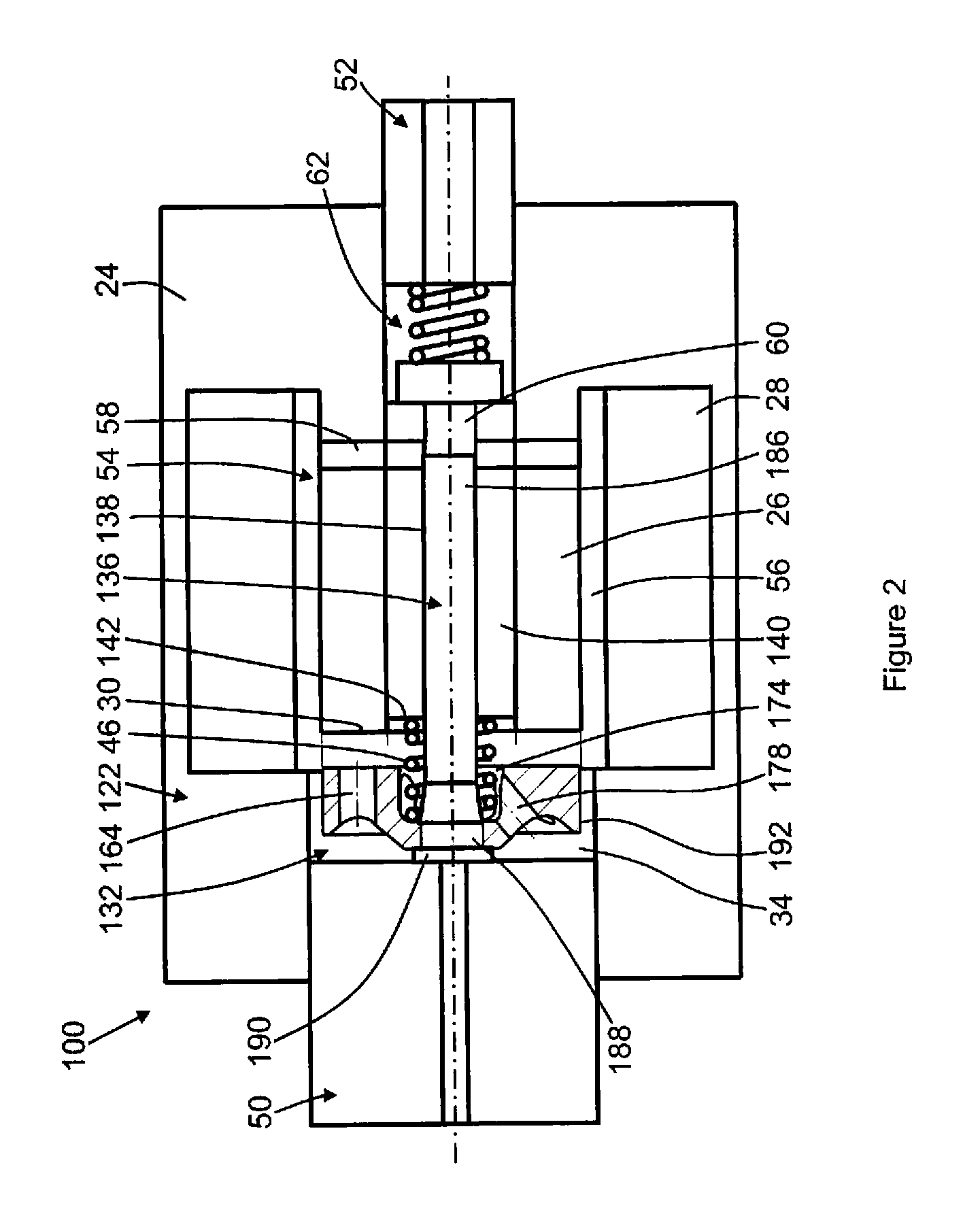
[0037]The pump 100 comprises an actuator 122 having an armature 132 according to the invention. Referring additionally to FIG. 3, the armature 132 comprises a generally disc-shaped body 168 defining a central axis (labeled P in FIG. 3) at the diametric centre of the disc. The armature 132 is made from a suitable soft magnetic material, such as a ferritic iron alloy. The armature includes a first face 170 that opposes the pole face 30 of the actuator, and a second face 172 opposite the first face 170.
[0038]A generally cylindrical recess 174 is provided in the first face 170 of the armature 132. The recess 174 is disposed coaxially with the body 168 of the armature 132. An aperture 176 extends from the recess 174 to the second face 172.
[0039]Vent holes 164 extend through the body 168 between the first and second faces 170, 172 in a direction parallel to the armature axis P. Only one such axial vent hole 164 is visible in FIGS. 2 and 3, but preferably several axial vent holes 164 are p...
second embodiment
[0055]As shown additionally in FIG. 5, in this second embodiment the armature 232 comprises a body 268, a first face 270 opposed to the pole face 30 of the actuator 54 in use, and a second face 272 opposite the first face 270.
[0056]A recess 274 is provided in the first face 270 to receive the upstream end of the spring 46. In this embodiment of the invention, a chamfered region 277 of the recess 274 connects the end face 275 and the peripheral wall 280 of the recess. The spring 46 abuts the generally planar end face 275 of the recess 274.
[0057]As in the first embodiment of the invention, the second face 272 of the armature 232 comprises an annular groove 282 disposed around a central land 284. An aperture 276 extends from the recess 274 to the second face 272. In use, the plunger 136 is received in the aperture 276 so as to prevent fluid flow through the aperture 276.
[0058]The armature 232 comprises five axial vent holes 264, arranged equi-angularly around the armature 232 and exten...
third embodiment
[0065]In this third embodiment of the invention, three channels 310 are provided in the second face 272 of the armature 332, to provide fluid communication means between the second face 272 and the recess 374 in the first face 370 of the armature 332. Additionally, six axial vent holes 364 are provided to allow fluid communication between the first and second faces 370, 372.
[0066]The channels 310 intersect three of the axial vent holes 364. The channels 310 can therefore extend deeper into the body 368 of the armature 332, so that the area of intersection between each channel 310 and the peripheral wall 380 of the recess 374 is larger than in the armature shown in FIGS. 4 and 5. The base 314 of each channel, which leads from the periphery of an axial vent hole 364 to the wall 380 of the recess, extends at an inclined angle with respect to the axis of the armature 332.
[0067]The chamfered region 377 between the end face 375 and the peripheral wall 380 of the recess 374 is absent in th...
PUM
 Abstract
Description
Claims
Application Information