Honeycomb structure body and method of designing honeycomb structure body

Active Publication Date: 2015-12-31
DENSO CORP
View PDF0 Cites 1 Cited by
  • Summary
  • Abstract
  • Description
  • Claims
  • Application Information

AI Technical Summary

Benefits of technology

[0013]In order to solve the problem and phenomenon previously described, the method according to an exemplary embodiment of the present invention designs, i.e. forms the cell density varying section, as the first cell density varying section, in at least a part of the honeycomb structure body. That is, the method designs, i.e. forms the honeycomb structure body having an improved structure in which a cell density in the cell density varying section is gradually decreased from a center point side to the outer periphery of the honeycomb structure body because a flow speed of exhaust gas reduces in the portion far from the central point. On the other hand, a flow speed of exhaust gas becomes high in the cells formed in the central portion when viewed in a cross section of the honeycomb structure body. Accordingly, it is possible to increase a cross sectional area of the flow passage in the cells formed in the cell density varying section according to approaching the outer periphery from the central point side in a radial direction of the honeycomb structure body. This improved structure of the honeycomb structure body allows exhaust gas to flow at a uniform flow sp

Problems solved by technology

However, the honeycomb structure body disclosed in the patent document 1 causes some problems.
The generation of distortion in shape of the cells reduces th

Method used


Image

  • Honeycomb structure body and method of designing honeycomb structure body
  • Honeycomb structure body and method of designing honeycomb structure body
  • Honeycomb structure body and method of designing honeycomb structure body

Examples


first exemplary embodiment

[0036]A description will now be given of the honeycomb structure body and the method of designing a structure of the honeycomb structure body according to a first exemplary embodiment with reference to FIG. 1 to FIG. 5.

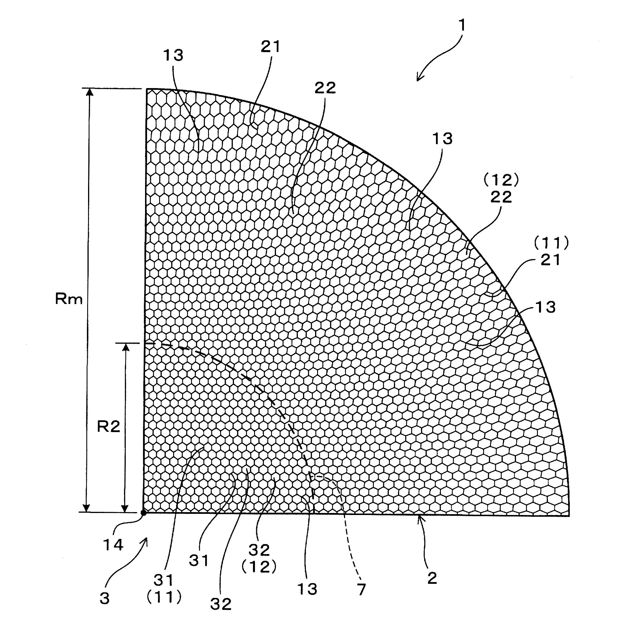
[0037]FIG. 1 is a cross sectional view showing a structure of the honeycomb structure body 1 according to the first exemplary embodiment in a radius direction which is perpendicular to an axial direction of the honeycomb structure body 1.

[0038]As shown in FIG. 1, the honeycomb structure body 1 according to the first exemplary embodiment has a plurality of cell walls 11, 21, 31 and a plurality of cells 12, 22, 32. Each of the cells 12, 22, 32 is surrounded by the cell walls. Although each of the cells 12, 22, 32 has a straight tubular shape, and a cross section of each has a hexagonal shape shown in FIG. 1, it is acceptable for each of the cells 12, 22, 32 to have a cross section of another shape, for example, a circular shape, a rectangle shape, a square shape, etc. T...

second exemplary embodiment

[0080]A description will be given of the structure of the honeycomb structure body 1 according to the second exemplary embodiment with reference to FIG. 7 and FIG. 8.

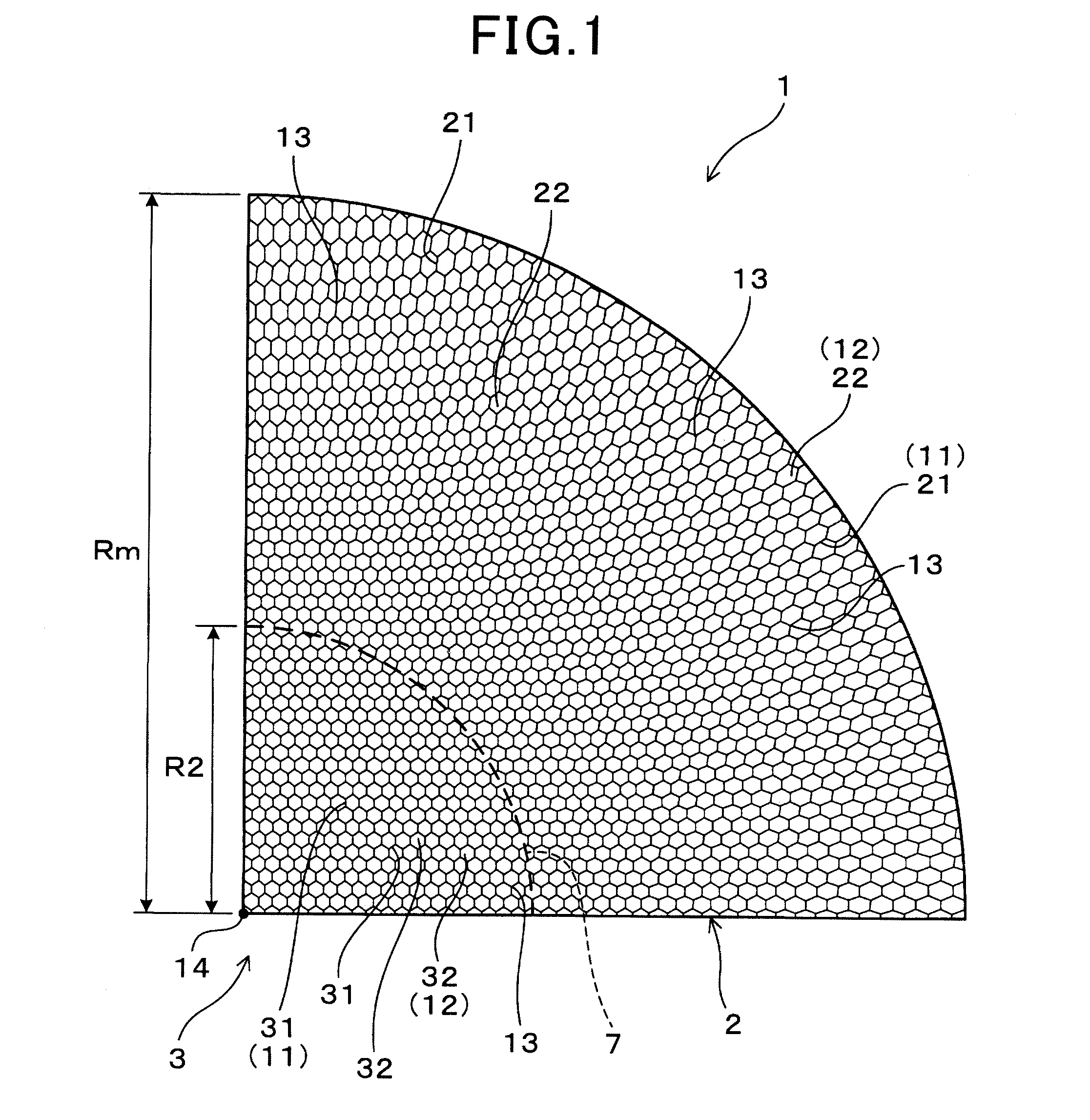
[0081]FIG. 7 is a cross sectional view showing a structure of a honeycomb structure body according to the second exemplary embodiment. FIG. 8 is a cross sectional view showing a structure of a base structure body to be used in the second exemplary embodiment.

[0082]As shown in FIG. 7 and FIG. 8, the honeycomb structure body 1 according to the second exemplary embodiment has a structure which is obtained by modifying the structural of the honeycomb structure body 1 according to the first exemplary embodiment. That is, the overall cells in the honeycomb structure body 1 according to the second exemplary embodiment are formed in the first cell density varying section 2 only.

[0083]The virtual base structure body 5 shown in FIG. 8 has the base cells 52 having a hexagonal tubular shape and the base cells 52 have a cell density...

third exemplary embodiment

[0087]A description will be given of the honeycomb structure body 1 according to a third exemplary embodiment.

[0088]FIG. 9 is a cross sectional view showing a structure of the honeycomb structure body 1 according to the third exemplary embodiment. FIG. 10 is a cross sectional view showing a structure of the virtual base structure body to be used for designing the honeycomb structure body 1 according to the third exemplary embodiment.

[0089]As shown in FIG. 9 and FIG. 10, the honeycomb structure body 1 according to the third exemplary embodiment has a structure obtained by modifying the structure of the honeycomb structure body 1 according to the second exemplary embodiment shown in FIG. 7 and FIG. 8. That is, the first cell density varying section 2 is formed in the overall area having the radius Rm measured from the central point 14 to the outermost periphery of the honeycomb structure body 1. A cell density of the cells formed in the cell density varying section 2 varies. That is, ...


PUM


Abstract

A honeycomb structure body has main cells having a tubular shape and main cell walls. Each main cell is surrounded by the main cell walls. A virtual base structure body has base cell walls and base cells. The honeycomb structure body has an improved structure obtained by modifying a structure of the virtual base structure body. Each base intersecting point, at which base cell walls intersect, is determined by a polar coordinate (r, θ) using a radius vector r and a deflection angle θ. Each main intersecting point is formed on a polar coordinate (r′, θ) using the deflection angle θ and a main radius vector r′ which is obtained by multiplying the radius vector r and a constant magnification without changing the deflection angle θ. A cell density varying section varies its cell density and is formed in at least a part of the honeycomb structure body.

Description

CROSS-REFERENCE TO RELATED APPLICATION[0001]This application is related to and claims priority from Japanese Patent Application No. 2014-133468 filed on Jun. 30, 2014, the contents of which are hereby incorporated by reference.BACKGROUND OF THE INVENTION[0002]1. Field of the Invention[0003]The present invention relates to honeycomb structure bodies and methods of designing a honeycomb structure body having an improved structure capable of allowing exhaust gas emitted from an internal combustion engine, etc. to flow at a uniform flow speed in overall cells, and to purify exhaust gas with high efficiency.[0004]2. Description of the Related Art[0005]There has been known a catalyst converter equipped with a honeycomb structure body capable of purifying exhaust gas emitted from an internal combustion engine mounted on vehicles, etc. Such a catalyst converter is arranged inside of an exhaust gas pipe connected to an internal combustion engine of a vehicle, for example. In general, the hon...

Claims


Application Information

Patent Timeline
IPC IPC(8): F01N3/28G06F17/50
CPCF01N2330/34F01N2330/60F01N2330/30G06F17/50F01N2330/48F01N3/2828G06F30/00
Inventor HAYASHI, NAOHIRO
Owner DENSO CORP
Why Eureka
Try Eureka