
Doorframe structure

Inactive Publication Date: 2007-02-08
CHUANG HSUN CHUAN
View PDF3 Cites 2 Cited by
  • Summary
  • Abstract
  • Description
  • Claims
  • Application Information

AI Technical Summary

Benefits of technology

[0012] The primary object of the invention is to provide an improved structure of a doorframe, which can be installed after completing the construction of the wall, thereby efficiently solving the inconvenience and disadvantages existent in the construction of the doorframe of the prior art.
[0013] Another object of the invention is to provide an improved structure of a doorframe, which can allow the doorframe made by molds, thus allowing interior upholstery more efficient and partition work more convenient.
[0014] To obtain the above objects, the improved structure of the doorframe according to the invention is provided with a doorframe, spring locks, and decorative panels fastened to the doorframe. The doorframe is provided with pluralities of fish-eye holes and grooves. By way of piercing screws through the fish-eye hoes, the doorframe is fastened to the pre-constructed holes on the wall. Each of the spring locks includes a base and an insertion locking device, which are installed inside the groove and on the backside of the decorative panel, respectively. By way of the spring locks, the decorative panels can be fastened to the doorframe to accomplish a novel doorframe structure.

Problems solved by technology

However, the following disadvantages do exist in the doorframe construction of the prior art:
The doorframe of the prior art must be installed during the construction of the wall, and the bricklayer and the doorframe installer must wait for and cooperate with each other, thus unable to work independently, rendering a waste of time and cost.
Furthermore, in case the doorframe is transformed seriously and the door is hard to close, repair and planning needed would be time-and-cost consuming.
As the doorframe of the prior art must be installed during the construction of the wall, it is easily damaged due to the crash by the other working staff during moving the doorframe.
After the completion of the interior partition work, the doorframe of the prior art cannot be shifted to other position, rendering inconveniences in interior design and upholstery.
Concluded above, it is obvious that inconveniences and disadvantages do exist in installation of the doorframe of the prior art, and there is a need in improvement of the structure thereof.

Method used


Image

  • Doorframe structure
  • Doorframe structure
  • Doorframe structure

Examples


Embodiment Construction

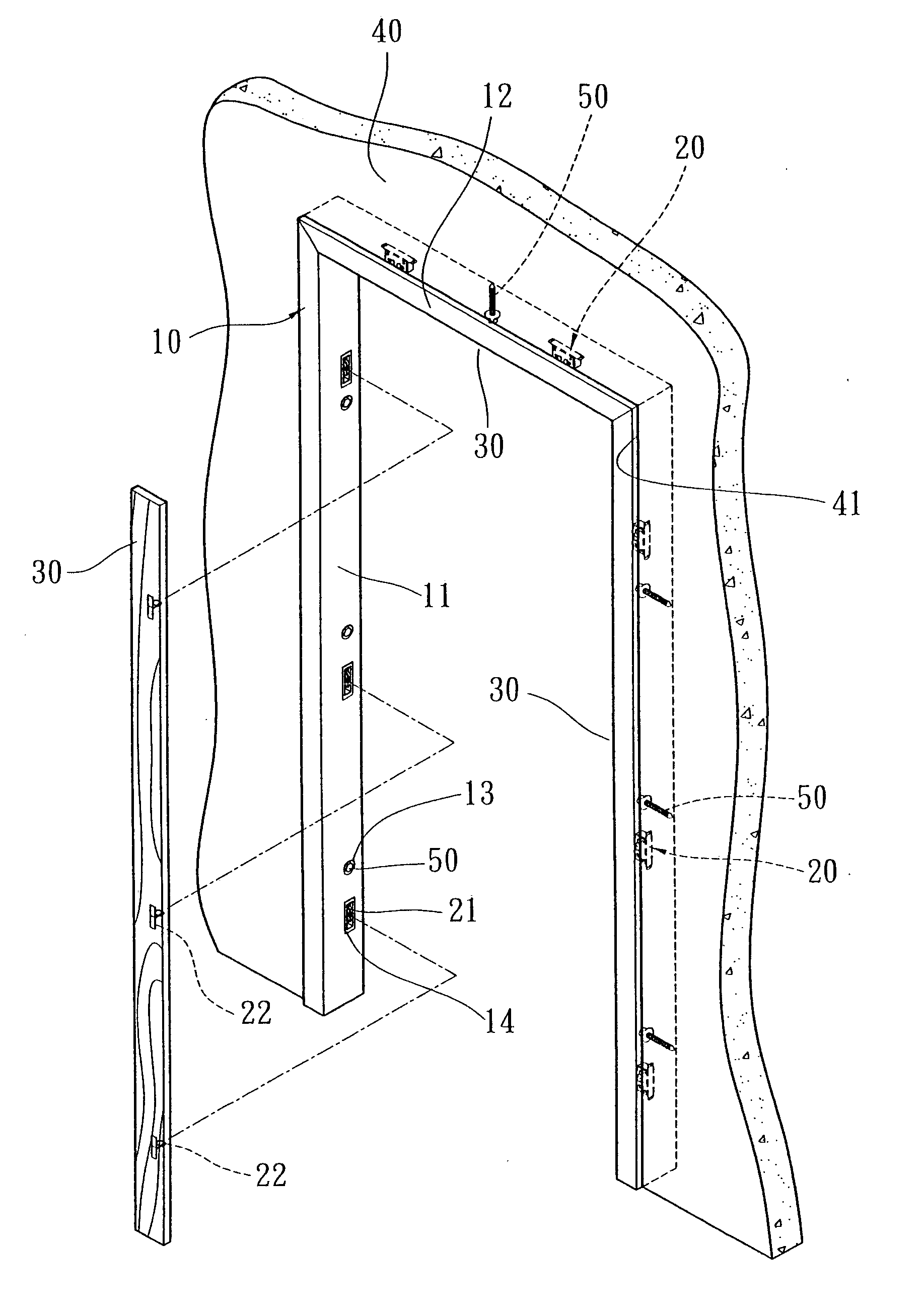
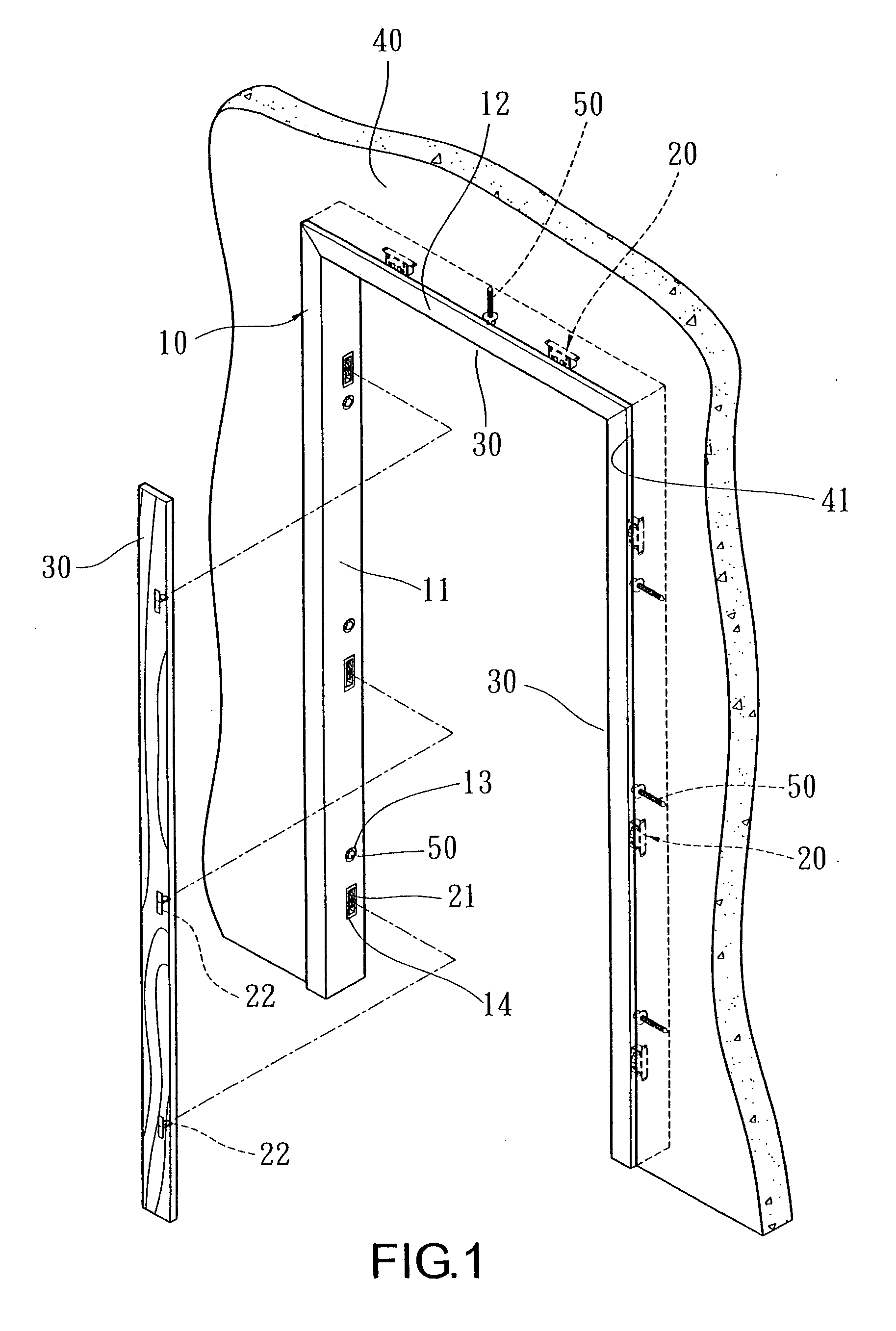
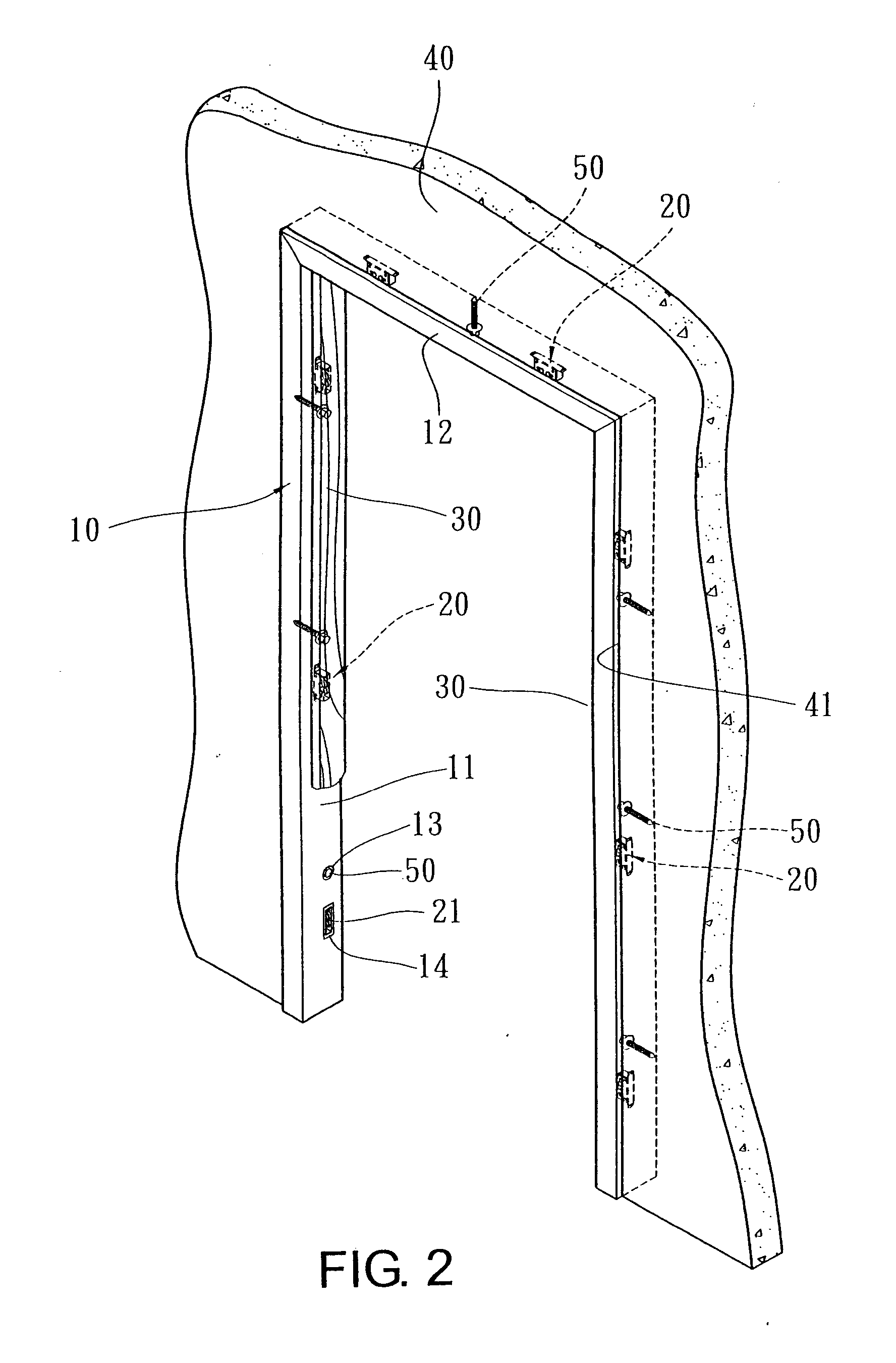
[0021] As shown in FIGS. 1 to 3, the invention relates to an improved structure of a doorframe, which is composed of a doorframe 10, spring locks 20, and decorative panels 30 fastened to the doorframe 10.

[0022] The doorframe 10 is composed of a pair of vertical jambs 11 and a cornice 12, all of which are provided with pluralities of fish-eye holes 13 and grooves 14 in a certain or uncertain distance.

[0023] Each of the spring locks 20 includes a base 21 and an insertion locking device 22. The base 21 is installed inside the groove via screws 23, while the insertion locking device 22 is fastened to the backside of the decorative panel 30, such that the insertion locking device 22 can be correspondingly inter-locked with the base 21.

[0024] The decorative panels 30 are prepared in coordination with the doorframe 10 on which the fish-eye holes 13 and grooves 14 are provided. By way of fastening the insertion locking devices 22 provided on the backside of the decorative panels 30 to th...


PUM


Abstract

A doorframe structure is composed of a doorframe, spring locks, and decorative panels fastened to the doorframe. The doorframe is provided with pluralities of fish-eye holes and grooves. By way of piercing screws through the fish-eye hoes, the doorframe is fastened to the pre-constructed holes on the wall. Each of the spring locks includes a base and an insertion locking device, which are installed inside the groove and on the backside of the decorative panel, respectively. By way of the spring locks, the decorative panels can be fastened to the doorframe to accomplish a novel doorframe structure. Accordingly, the doorframe structure can be installed after the wall has been completed constructed, thus avoiding the inconvenience occurred in construction of the doorframe of the prior art, i.e., the doorframe must be installed before completing the construction of the wall.

Description

BACKGROUND OF THE INVENTION [0001] (a) Field of the invention [0002] The present invention relates to a doorframe structure, particularly to a doorframe that can be installed after completing the construction of the wall. [0003] (b) Description of the Prior Art [0004] In constructing a doorframe of the prior art, the doorframe must be installed before the partition wall has been completed. As shown in FIG. 5, a doorframe 10a is connected via supporters 11a, such that the doorframe 10a can be in a rectangular form. Besides, while long nails 12a are pre-provided to pierce out of the doorframe 10a, the bricklayer would have the bricks and cement hold the long nails 12a at the time of building the wall, thereby the doorframe 10a would be fastened to the pre-determined position of the wall 20a (or the concrete structure). Thereafter, bricks or concrete is filled up the crevice between the doorframe and the wall. Subsequently, the wall is polished and painted, and finally the surface of t...

Claims


Application Information

Patent Timeline
IPC IPC(8): E06B1/04
CPCE06B1/06E06B1/6015E06B1/34
Inventor CHUANG, HSUN-CHUAN
Owner CHUANG HSUN CHUAN
Learn More