Method and apparatus for treating a malformed eustachian tube

Pending Publication Date: 2019-03-21
DOMESTIC ASSET LLP
View PDF1 Cites 1 Cited by
  • Summary
  • Abstract
  • Description
  • Claims
  • Application Information

AI Technical Summary

Benefits of technology

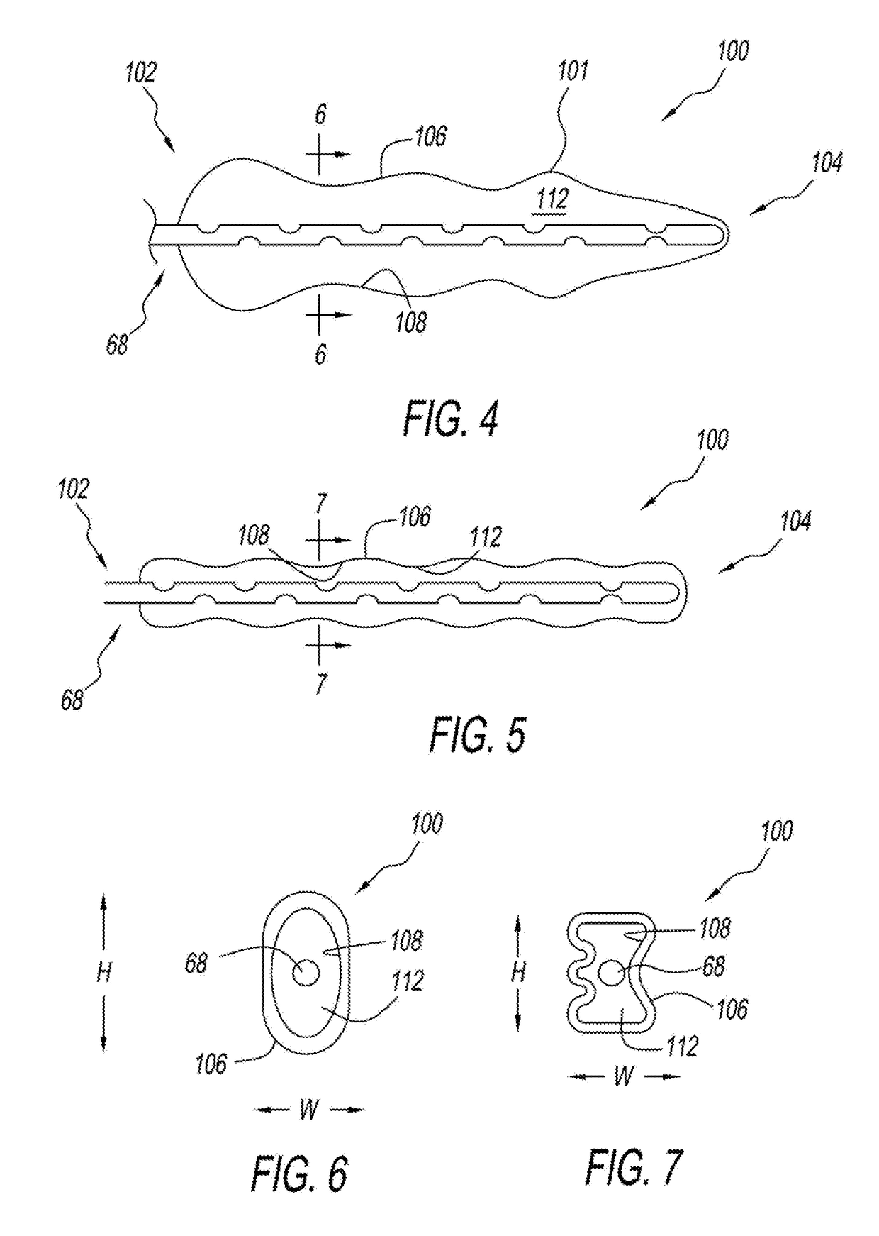
[0028]When in its inflated position, the balloon is designed to have a cross sectional area that is slightly larger than the cross section of the Eustachian tube, so that the balloon can exert a radially outwardly directed pressure against the walls of the Eustachian tube. Through the exertion of this pressure against the walls of the Eustachian tube, the cartilaginous walls of the Eustachian tube can be moved radially outwardly, to thereby expand the cross-sectional area of the passageway of the Eustachian tube.
[0029]The balloon is held in place within the Eustachian tube for a sufficiently long enough period of time, to permit the balloon to exert a sufficient force for a long enough time against the walls of the Eustachian tube, to

Problems solved by technology

Pressure differences between atmosphere and the middle ear can cause temporary conductive hearing loss by decreasing the motion of the tympanic membrane and ossicles of the ear.
Ear infections are common in some children because the Eustachian tube is not fully functional.
Additionally, since the Eustachian tube has a smaller diameter in children, the movement of air within the Eustachian tube becomes more difficult, thus making the Eustachian tube more susceptible to clogging.
Further, the not-yet-fully-developed nature of children's immune systems, along with their poor hygiene habits often makes children more prone to upper respiratory infections than adults.
This disorder may result in a large amount of mucus accumulating in the middle ear, which often impairs hearing to a degree.
The sizes of the Eustachian tubes discussed above would not function well on children, as the Eustachian tubes of children likely have a smaller cross sectional area than adults.
However, currently such procedures are not being done on children because they are believed at the present time to create too much of a medical-legal risk.
In particular, one problem with current cylindrical tubes is that

Method used


Image

  • Method and apparatus for treating a malformed eustachian tube
  • Method and apparatus for treating a malformed eustachian tube
  • Method and apparatus for treating a malformed eustachian tube

Examples


Example

[0046]The description that follows describes, illustrates and exemplifies one or more particular embodiments of the present invention in accordance with its principles. This description is not provided to limit the invention to the embodiment or embodiments described herein, but rather to explain and teach the principles of the invention in such a way to enable one of ordinary skill in the art to understand these principles and, with that understanding, be able to apply them to practice not only the embodiment or embodiments described herein, but also other embodiments that may come to mind in accordance with these principles.

[0047]The scope of the present invention is intended to cover all such embodiments that may fall within the scope of the appended claims, either literally or under the doctrine of equivalents.

[0048]It should be noted that in the description and drawings, like or substantially similar elements may be labeled with the same reference numerals. However, sometimes t...


PUM


Abstract

A balloon is provided for insertion into a mammalian eustachian tube. The balloon is a high pressure balloon having a body including a proximal end, a distal end, an exterior surface and an interior surface defining an air receivable interior. The body having a plurality of segments of different cross sectional areas, and a non-circular cross sectional profile. The balloon is inflatable between a deflated configuration and an inflated configuration. The body is sufficiently inelastic so as to be substantially incapable of expanding beyond a pre-determined size and shape when in the inflated configuration. The segments include a first segment having a first cross sectional area and a second segment disposed distally of the first segment The second segment has a second cross sectional area larger than the first cross sectional area.

Description

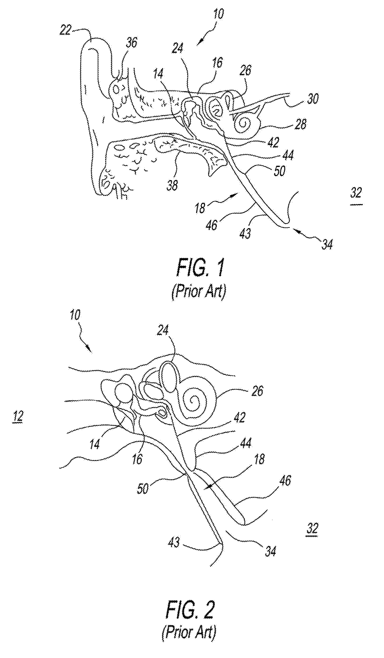
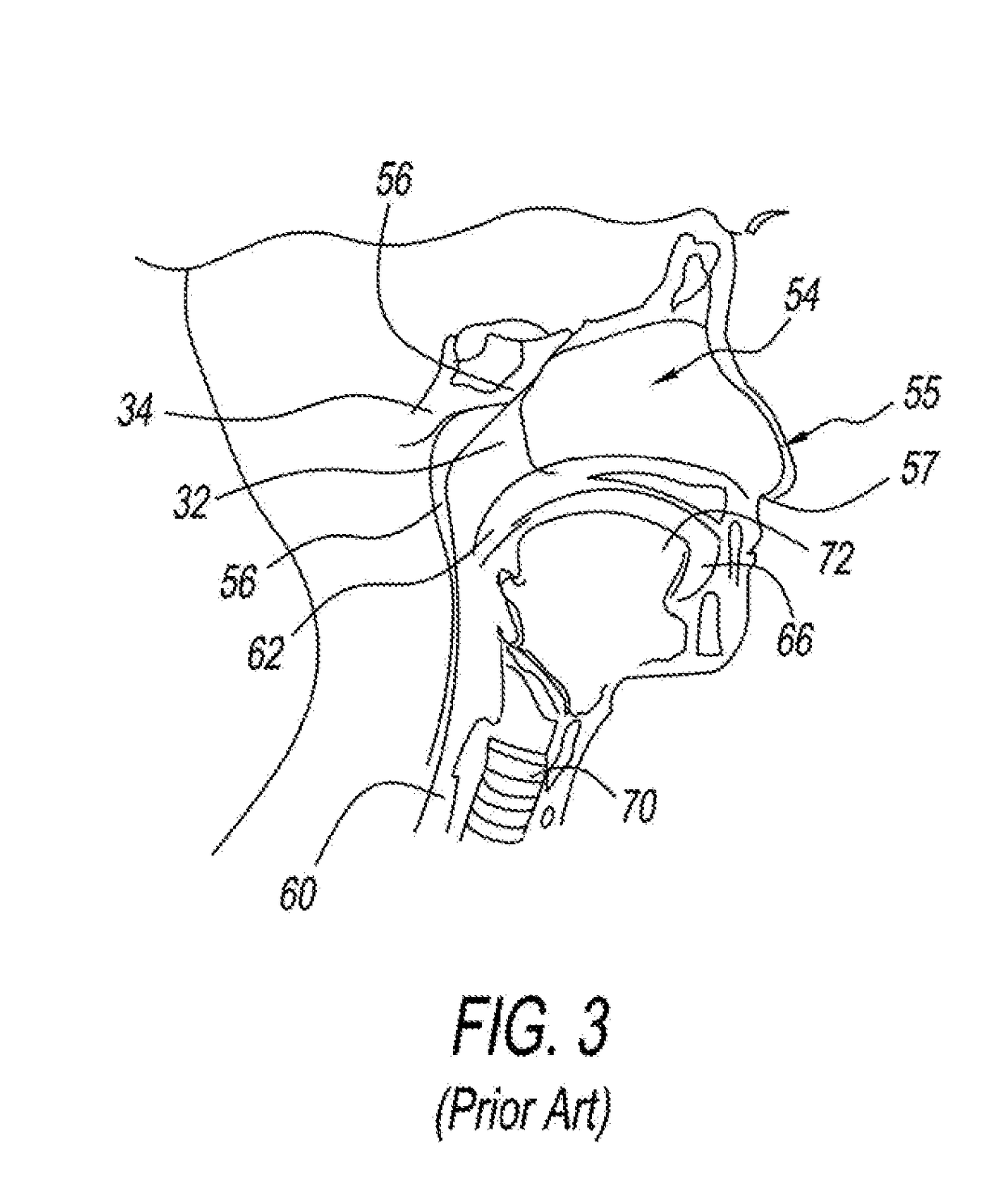
CLAIM OF PRIORITY[0001]The instant application claims benefit of priority to Michael H. Fritsch, U.S. Provisional Patent Application No. 62 / 561,117, that was filed on 20 Sep. 2017 for a DEVICE FOR USE IN PERFORMING A EUSTACHIAN TUBE, which patent application is incorporated by reference herein in its entirety.I. TECHNICAL FIELD OF THE INVENTION[0002]The present invention relates to methods for treating diseases of the ear, and in particular, devices and methods for treating pathologies associated with the Eustachian tube of the ear.II. BACKGROUND OF THE INVENTION[0003]The Eustachian tube is also known as the auditory tube or the pharyngotympanic tube. The Eustachian tube links the Nasopharynx to the middle ear. It is a part of the middle ear, and in adult humans, is approximately 35 mm long.[0004]The Eustachian tube extends at its lateral end, from the anterior wall of the middle ear to its medial end at the lateral ear of the Nasopharynx, as shown in FIGS. 1-3. The Eustachian tube ...

Claims


Application Information

Patent Timeline
IPC IPC(8): A61F11/00A61M29/02
CPCA61F11/002A61M29/02A61B2018/00327A61M2210/0675A61M25/1002A61F11/202
Inventor FRITSCH, MICHAEL H
Owner DOMESTIC ASSET LLP
Why Eureka
Try Eureka