
Surface cleaning apparatus

Active Publication Date: 2020-01-23
OMACHRON INTPROP
View PDF0 Cites 3 Cited by
  • Summary
  • Abstract
  • Description
  • Claims
  • Application Information

AI Technical Summary

Benefits of technology

This patent text describes a surface cleaning apparatus that can be made smaller without compromising its ability to clean. The apparatus has a cyclone chamber with a large number of airflow passages that allow dirty air to enter the chamber. This arrangement reduces the height of the cyclone inlet and improves the efficiency of the cyclone separation. Additionally, it allows for a common airflow passage that ensures a constant supply of dirty air into the apparatus. Overall, this design improves the performance of the surface cleaning apparatus while keeping it compact.

Problems solved by technology

This often requires taller cyclone inlets, resulting in a corresponding increase in the height of the cyclone chamber.

Method used


Image

  • Surface cleaning apparatus
  • Surface cleaning apparatus
  • Surface cleaning apparatus

Examples


Embodiment Construction

[0091]Various apparatuses, methods and compositions are described below to provide an example of an embodiment of each claimed invention. No embodiment described below limits any claimed invention and any claimed invention may cover apparatuses and methods that differ from those described below. The claimed inventions are not limited to apparatuses, methods and compositions having all of the features of any one apparatus, method or composition described below or to features common to multiple or all of the apparatuses, methods or compositions described below. It is possible that an apparatus, method or composition described below is not an embodiment of any claimed invention. Any invention disclosed in an apparatus, method or composition described below that is not claimed in this document may be the subject matter of another protective instrument, for example, a continuing patent application, and the applicant(s), inventor(s) and / or owner(s) do not intend to abandon, disclaim, or d...


PUM


Abstract

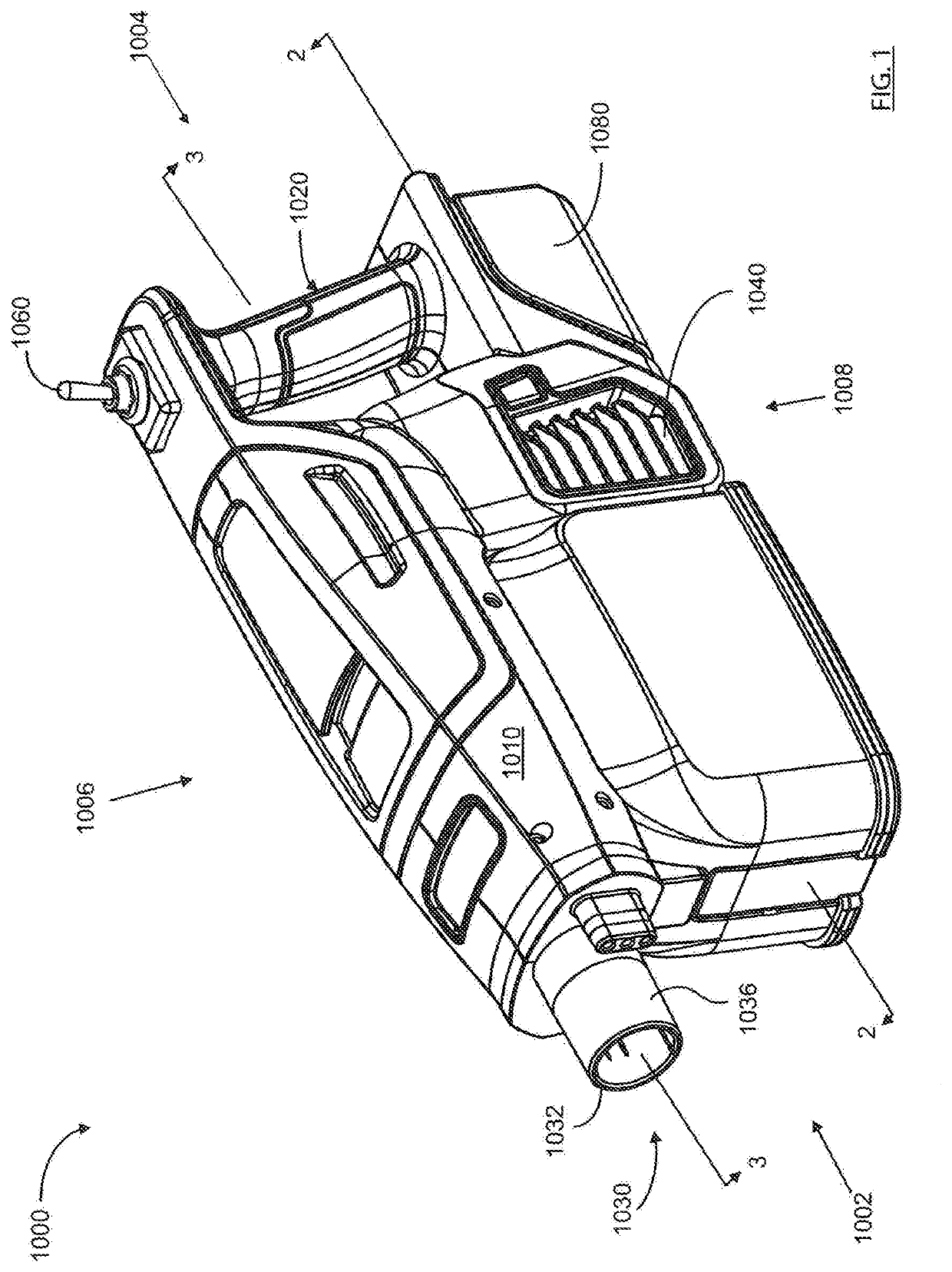
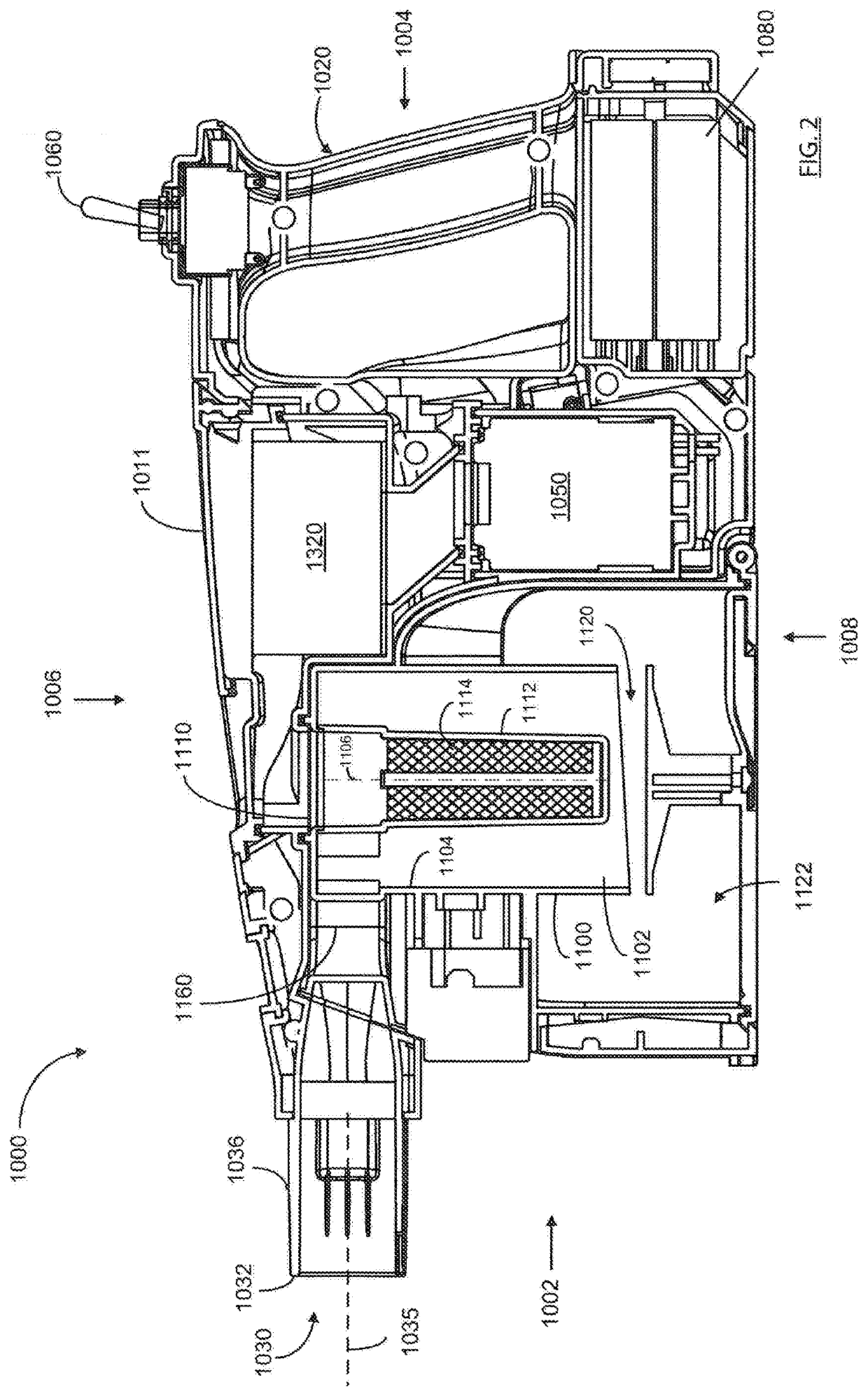
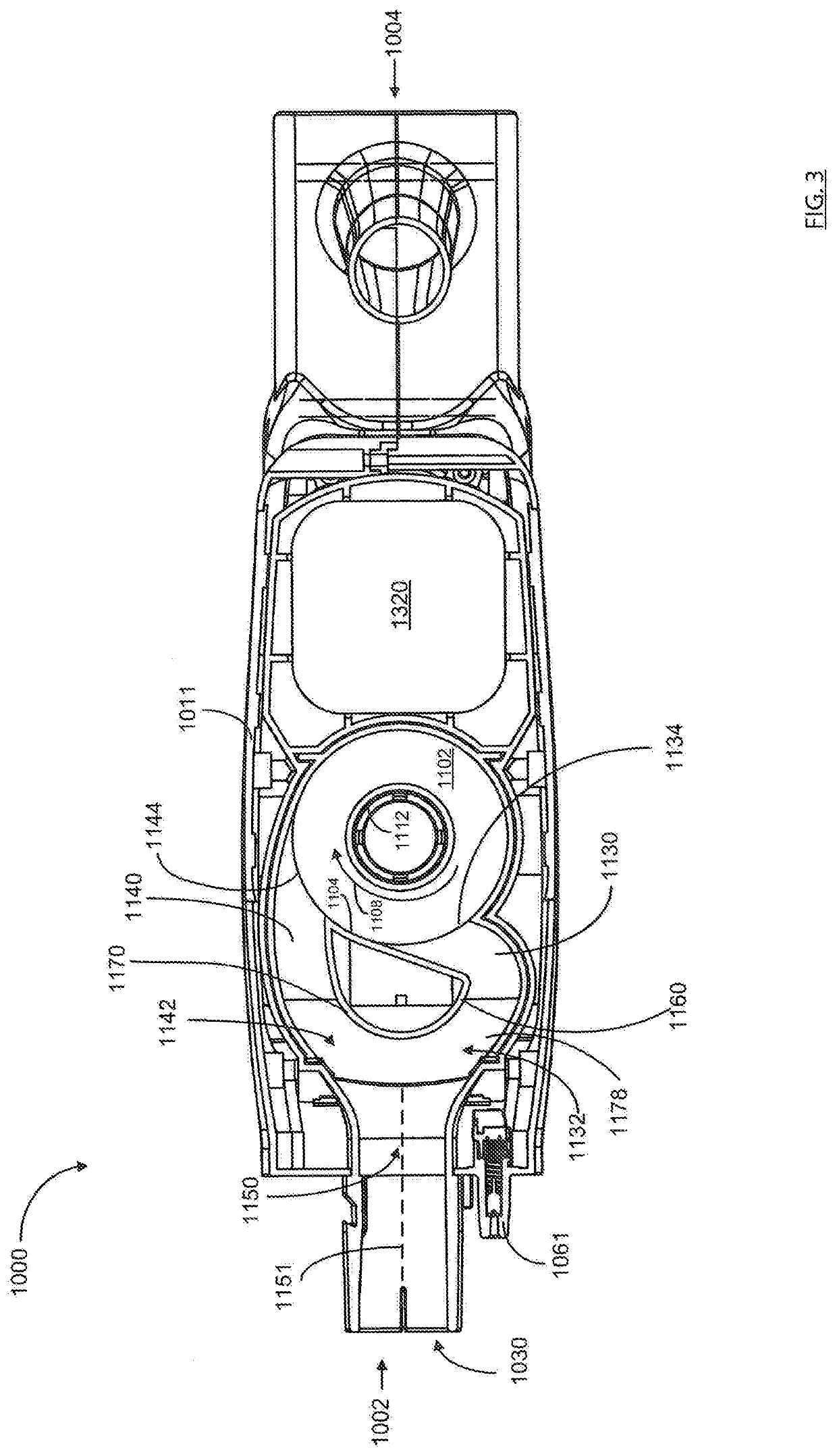
A surface cleaning apparatus has a first air flow path extending from a dirty air inlet to a clean air outlet with a suction motor and a cyclone positioned in the first air flow path. The cyclone has a cyclone chamber, a first airflow passage, and a second airflow passage. The first airflow passage defines a first tangential air inlet to the cyclone chamber and the second airflow passage defines a second tangential air inlet to the cyclone chamber. The airflow path includes a common airflow passage upstream of the first and second airflow passages and an axis of the common airflow passage intersects the cyclone chamber. At least a portion of the first tangential air inlet is positioned upstream from a location at which the common airflow passage axis intersects the cyclone chamber.

Description

FIELD[0001]This disclosure relates generally to surface cleaning apparatus such as hand vacuum cleaners, upright vacuum cleansers, stick vacuum cleaners or canister vacuum cleaners, and in particular surface cleaning apparatus with multi-inlet cyclone chambers.INTRODUCTION[0002]The following is not an admission that anything discussed below is part of the prior art or part of the common general knowledge of a person skilled in the art.[0003]Various types of surface cleaning apparatus are known, including upright surface cleaning apparatus, canister surface cleaning apparatus, stick surface cleaning apparatus, central vacuum systems, and hand carriable surface cleaning apparatus such as hand vacuums. Further, various designs for cyclonic surface cleaning apparatus are known in the art, including cyclonic hand vacuum cleaners.[0004]Cyclones may have an axial inlet or a tangential inlet. Further a cyclone may have multiple inlets which are fed by a single chamber. See for example US201...

Claims


Application Information

Patent Timeline
IPC IPC(8): A47L9/16A47L5/16A47L9/06
CPCA47L9/1616A47L5/16A47L9/1683A47L9/165A47L9/1691A47L9/0606A47L5/24A47L9/122A47L9/1608A47L9/1666A47L9/246A47L9/2857A47L9/1625A47L9/24B04C5/04Y10S55/03
Inventor CONRAD, WAYNE ERNEST
Owner OMACHRON INTPROP
Learn More