Reverse osmosis water filtering system

Active Publication Date: 2010-05-13
WATTS REGULATOR
28 Cites 14 Cited by

AI-Extracted Technical Summary

Problems solved by technology

Although these storage tanks are widely used and provide a suitable means for storing permeate, the storage tanks do have a significant drawback.
Accordingly, in order to completely fill the stora...

Benefits of technology

[0012]The present disclosure provides a new and improved RO water filtering system. Among other aspects and advantages, the RO water filtering system of the present disclosure includes an improved permeate storage arrangement that reduces backpressu...

Abstract

A valve assembly having a first valve defining an inlet connected to the inlet supply and an outlet connected to the concentrate chamber, a second valve defining an inlet connected to the permeate chamber and an outlet connected to the faucet, and a third valve defining an outlet connected to drain, a port connected to the concentrate chamber, and an inlet connected to the inlet supply. The port is selectively in fluid communication with the third valve outlet and inlet. When the faucet opens, the first valve opens, the second valve has permeate flowing, and the third valve opens a flowpath between the third valve port and the inlet due to pressure dropping in the second valve. When the faucet closes, the first valve closes and the third valve opens another flowpath between the third valve port and outlet due to pressure created in the second valve.

Application Domain

Servomotor componentsTreatment involving filtration +12

Technology Topic

EngineeringMechanical engineering +2

Image

  • Reverse osmosis water filtering system
  • Reverse osmosis water filtering system
  • Reverse osmosis water filtering system

Examples

  • Experimental program(1)

Example

[0035]The present invention overcomes many of the prior art problems associated with reverse osmosis (RO) filtering systems. The advantages, and other features of the RO filtering systems disclosed herein, will become more readily apparent to those having ordinary skill in the art from the following detailed description of certain preferred embodiments taken in conjunction with the drawings which set forth representative embodiments of the present invention and wherein like reference numerals identify similar structural elements.
[0036]Additionally, the illustrated and described embodiments can be understood as providing, exemplary features of varying detail of certain embodiments, and therefore, features, components, modules, elements, and/or aspects of the illustrations can be otherwise combined, interconnected, sequenced, separated, interchanged, positioned, and/or rearranged without materially departing from the disclosed systems or methods. Further, the shapes and sizes of components are also somewhat schematic for exemplary purposes and can be altered without materially affecting or limiting the disclosed technology.
[0037]For clarity, common items such as conduits, tubing interconnections and interconnections have not been specifically included, represented schematically in the Figures or shown and not described in any detail as would be appreciated by those of ordinary skill in the pertinent art. All relative descriptions herein such as left, right, up, and down are with reference to the Figures, and not meant in a limiting sense.
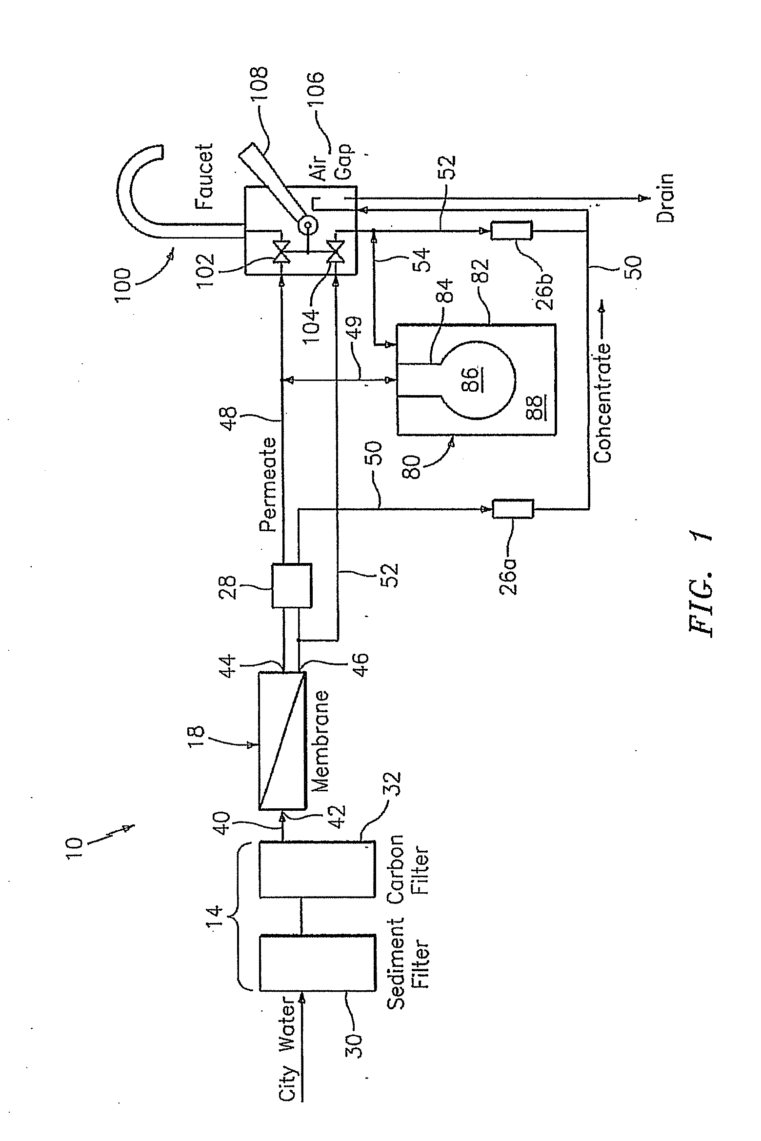
[0038]FIG. 1 shows an exemplary embodiment of a new and improved RO water filtering system 10 constructed in accordance with the present disclosure. Intake water enters the filtering system 10 from a water source, such as city water, and is routed there through. The RO water filtering system 10 generates purified water or permeate for dispensing from a faucet assembly 100 and waste or concentrate water that is ultimately rejected to drain.
[0039]In brief overview, the system 10 includes a filter assembly 14 for initially removing sediment and contaminants. The filter assembly 14 can include a sediment filter 30 and a carbon filter 32. After passing through the filter assembly 14, the filtered water passes a RO membrane 18 that creates permeate and concentrate water. A storage tank 80 accumulates the permeate while using the concentrate water to selectively create pressure upon the stored permeate. The RO water filtering system 10 also includes an auxiliary faucet assembly 100 that works with flow restrictors 26a and 26b and a shut-off valve 28 to control the output of the RO water filtering system 10. Flow restrictor 26b an off the shelf component that allows using a majority of off the shelf components in the system 10 with the exception of the faucet as would be recognized after review of the discussion below.
[0040]The storage tank 80 includes an outer container 82 housing an expandable resilient bladder 84. The expandable bladder 84 forms a permeate storage chamber 86, while a concentrate water chamber 88 is formed between the bladder 84 and the outer container 82. Because the bladder 84 is flexible and expands, pressure equalizes within the tank 80 generally. Thus, higher pressure in the concentrate chamber 88 will urge permeate from the storage chamber 86 and lower pressure in the concentrate chamber 88 reduces and/or removes resistance on permeate into the permeate storage chamber 86. In one embodiment, the bladder 84 is fabricated from an elastomeric material.
[0041]The RO membrane 18 includes three ports: an intake port 42, a permeate outlet port 44, and a concentrate outlet port 46. The intake port 42 receives filtered intake water from the filter assembly 14 through a water tube 40. The permeate is routed from the outlet port 44 through the shut-off valve 28 and permeate tube 48 and to a first valve 102 of the faucet assembly 100. The permeate is also diverted through a permeate diverter tube 49 to the permeate storage chamber 86 of the storage tank 80 to be stored under pressure until the valve 102 of the faucet assembly 100 is opened.
[0042]When the valve 102 is opened by a user, permeate is forced from the tank 80 and out the faucet assembly 100. The combination of intake pressure differential and pressure from the concentrate water contained in the concentrate water chamber 88 provides excellent outflow of permeate.
[0043]Concentrate water is routed from the outlet port 46 through the shut-off valve 28 and a primary concentrate tube 50, and then through an air gap 106 of the faucet for subsequent disposal down drain 110. One of the flow restrictors 26a is provided in the primary concentrate tube 50.
[0044]The shut-off valve 28 is automatic and is adapted to stop the flow of concentrate water through to the primary concentrate tube 50 when the permeate storage chamber 86 of the tank 80 becomes full of permeate and pressure within the permeate tube 48 rises past a predetermined level indicating that the permeate storage chamber 86 is full. The blocked primary concentrate tube 50 prevents additional filtered water from entering the intake port 42 of the RO membrane and prevents the production of additional permeate.
[0045]A secondary concentrate tube 52 branches off from the primary concentrate tube 50 between the RO membrane 18 and the shut-off switch 28. The secondary concentrate tube 52 is routed through a second valve 104 of the faucet assembly 100 and connects back to the primary concentrate tube 50 between the first flow restrictor 26a and the air gap 106 of the faucet assembly 100. The other of the flow restrictors 26a is provided in the secondary concentrate tube 52.
[0046]A concentrate diverter tube 54 connects the concentrate water chamber 88 of the tank 80 to the secondary concentrate tube 52 between the second valve 104 and the second flow restrictor 26b. The valves 28, 102, 104 may be any kind of valve now known and later developed such a diaphragm, a pin valve, a ball valve, a gate valve, a globe valve, or a butterfly valve. Although not shown explicitly, the branching of the various tubes could be by several means such as diverters or T-shaped fittings.
[0047]The faucet assembly 100 includes a lever 108 that controls both of the first and second valves 102, 104 of the faucet assembly 100, such that the valves 102, 104 are substantially simultaneously opened and closed. During operation with the valves 102, 104 closed, the RO water filtering system 10 operates until the permeate storage chamber 86 is full and the shut-off switch 28 closes the primary concentrate tube 50. At this point, the permeate storage chamber 86 is at its largest volume while the concentrate chamber 88 of the tank 80 is at its smallest volume, with excess concentrate water being expelled from the concentrate chamber 88, through the second flow restrictor 26b and the air gap 106, and down the drain. Throughout the expansion of the permeate storage chamber 86, backpressure advantageously remains low while the efficiency of the RO membrane remains high because of the expulsion of the concentrate water from the concentrate chamber 88.
[0048]When the lever 108 of the faucet assembly 100 is opened, both valves 102, 104 are opened. Permeate is directed from the permeate storage chamber 86 to the faucet assembly 100 by the open first valve 102, while concentrate water is directed through tubes 52, 54 to the concentrate chamber 88 by the open second valve 104. The concentrate water flowing into the concentrate chamber 88 provides additional pressure for expelling the permeate from the permeate storage chamber 86. As a result, the exit flow from the faucet assembly 100 is adequately maintained as the permeate storage chamber 86 empties.
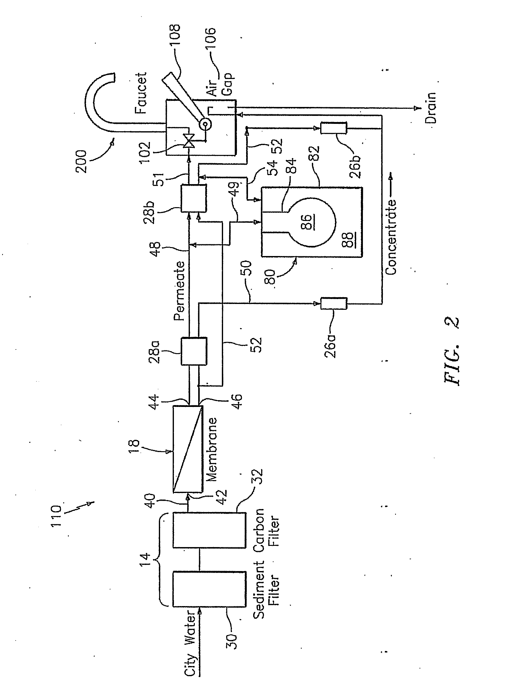
[0049]FIG. 2 shows another exemplary embodiment of a new and improved RO water filtering system 110 constructed in accordance with the present disclosure. The embodiment 110 of FIG. 2 is similar to the embodiment 10 of FIG. 1 such that similar elements have the same reference number. The filtering system 110 uses concentrate to provide pressure, thus similar to above, water is not wasted as compared to systems that use intake water to pressurize. Further, the filtering system 110 desirably uses standard components like diaphragm valves and flow restrictors to accomplish the objectives.
[0050]A primary difference of the water filtering system 110 is the use of two shut-off valves 28a and 28b with a modified auxiliary faucet assembly 200. The faucet assembly 200 includes only one valve 102 for controlling flow of the permeate. Accordingly, when the lever 108 is actuated to dispense permeate, the permeate in the tank 80 is urged out of the faucet assembly 200. It is envisioned that the faucet assembly 200 could be any device for using or dispensing purified water such as an ice-maker or other application. Commonly, the faucet assembly 200 and ice-maker would both receive permeate from the system 110.
[0051]As shown, the second shut-off valve 28b is connected in the permeate path between the RO membrane 18 and faucet assembly 200. Tubing 51 connects the permeate output of the shut-off valve 28b to the faucet valve 102. In the concentrate path, the second shut-off valve 28b is connected between the RO membrane 18 and the concentrate chamber 88 with the secondary concentrate tube 52 passing to drain and having a concentrate diverter tube 54 branch to bring the concentrate to the concentrate chamber 88 of the tank 80. Shut-off valves 28a, 28b may be the exact same part. In a preferred embodiment, the shut-off valves 28a, 28b close upon the exit pressure being two thirds of the inlet pressure.
[0052]In operation, the shut-off valve 28b responds to pressure changes. When the lever 108 opens, the pressure drops in tubing 51 to open the shut-off valve 28b to allow permeate and concentrate water to flow there through. As a result, concentrate water flows into the concentrate chamber 88 via the diverter tube 54 to urge the permeate water in the permeate storage chamber 86 into diverter tube 49 and ultimately out the faucet 200. For the time that the faucet is open, the flow restrictor 26b also creates some bleeding to drain, but the flow restrictor 26b is sized so that the bleed level is acceptable. Upon closing the lever 108, the pressure builds in tubing 51 so that the shut-off valve 28b closes. With the shut-off valve 28b closed, the permeate passes into the permeate storage chamber 86. The concentrate chamber 88 is still open to drain via tubing 52, 54. The flow restrictor 26b drains more quickly than the RO membrane 18 makes permeate so that the system back pressure is minimal, if any, and the efficiency of the RO membrane 18 is improved. As a result of the minimal back pressure, the permeate not only replenishes quickly without resistance, a fast wash effect occurs at the RO membrane 18. In other words, the increased flow across the RO membrane has a cleaning effect.
[0053]Referring now to FIG. 3, another exemplary embodiment of a new and improved RO water filtering system 210 constructed in accordance with the present disclosure is shown. The RO water filtering system 210 is similar to the embodiments 10, 110 of FIGS. 1 and 2 such that similar elements have the same reference number. The filtering system 210 takes advantage of a new valve assembly 220, which controls four flow paths.
[0054]In brief overview, the valve assembly 220 includes three sub-assembly valves 222a-c. A first sub-assembly valve 222a defines an inlet 224a connected to the inlet supply and an outlet 224b connected to the concentrate chamber 88. A second sub-assembly valve 222b defines an inlet 224c connected to the permeate chamber 86 and an outlet 224d connected to the faucet 200. A third sub-assembly valve 222c defines an outlet 224e connected to drain, a port 224f connected to the concentrate chamber 86, and an inlet 224g connected to the inlet supply. The port 224f is selectively in fluid communication with the third sub-assembly outlet 224e and inlet 224g.
[0055]When the faucet is open, the first sub-assembly valve 222a opens to create a first flowpath A at least in part due to pressure dropping in the second sub-assembly valve 222b, the second sub-assembly valve 222b opens a second flowpath B with the permeate flowing there through, and the third sub-assembly valve 222c is opens a third flowpath C between the third sub-assembly port 224f and the inlet224g at least in part due to pressure dropping in the second sub-assembly valve 222b.
[0056]When the faucet is closed, the first sub-assembly valve 222a is closed at least in part due to pressure created in the second sub-assembly valve 222b, the second sub-assembly valve 222b has no flow, and the third sub-assembly valve 222c is set to open a fourth flowpath D between the third sub-assembly port 224f and outlet 224e at least in part due to pressure created in the second sub-assembly valve 222b. It is noted that several interconnections such as tubing function to complete more than one flowpath A, B, C or D as noted in the Figures.
[0057]Referring additionally to FIGS. 4 and 5, isolated cross-sectional views of the valve assembly 220 are shown in the faucet open and closed positions, respectively. The first flowpath A passes through the first sub-assembly valve 222a of the valve assembly 220 from the inlet supply water to the concentrate chamber 88 of the tank 80. When the faucet is closed, the first flowpath A is normally closed. However, when the faucet is open, the first flowpath A opens to provide the inlet supply water to the concentrate chamber 88 for helps to pressurize the permeate chamber 86 of the tank 80 and, in turn, effectively dispense permeate from the faucet 200.
[0058]Referring still to FIG. 3, when the first flowpath A is open as shown in FIG. 5, the inlet water passes through the membrane 18 to a first T-connector 226a, which provides the inlet water to port 224a on the first sub-assembly valve 222a of the valve assembly 210. The inlet water supply exits port 224b, passes through a flow restrictor 228, through a second T-connector 226b and into the concentrate chamber 88 of the tank 80 via port 224f as described in more detail below.
[0059]The second flowpath B of the valve assembly 220 passes through the second sub-assembly valve 222b from the permeate chamber 86 of the tank 80 to the faucet 200. When the faucet 200 is closed (see FIG. 6), the second flowpath B is normally closed. However, when the faucet 200 is open (see FIG. 7), the second flowpath B opens so that permeate passes from the permeate chamber 86 of the tank 80 out of the faucet 200. Ports 224c, 224d of the second sub-assembly valve 222b effectively couple the valve assembly 220 into the second flowpath B. The permeate flows from the permeate chamber 86 of the tank 80, through a third T-connector 226c and a final filter 230, and into port 224c on the second sub-assembly valve 222b of the valve assembly 220. The permeate then exits port 224d of the second sub-assembly valve 222b and passes out the faucet 200.
[0060]The third sub-assembly valve 222c completes either the third flowpath C or the fourth flowpath D. When the faucet 200 is open, the third flowpath C opens to provide inlet supply water into the concentrate chamber 88 to pressurize the permeate chamber 86 of the tank 80. The third flowpath C inlet supply water passing through the first T-connector with inlet 224g of the third sub-assembly valve 222c. The inlet supply water exits via port 224f and passes through the second T-connector 226b into the concentrate chamber 88.
[0061]When the faucet is closed, the third sub-assembly valve 222c opens the fourth flowpath D to connect the concentrate chamber 88 to drain. As a result, concentrate flows from the concentrate chamber 88, through the second T-connector into port 224f. The concentrate then exits via outlet 224e to drain relieving the tank pressure on the permeate chamber 86 so that the membrane can function with little or no back pressure.
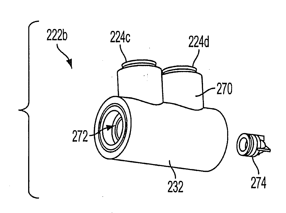
[0062]Referring to FIGS. 6-7C, perspective and exploded views of the valve assembly 220 are shown. The valve assembly 220 includes an outer housing 232 preferably formed from multiple components although the housing 232 may also be unitary. The housing 232 forms the ports 224a-g for coupling to the other system components. The ports 224a-g contain collets and other well-known, seals, fittings and connectors that are not described in detail for brevity. The housing 232 also defines an interior for containing the working components of the three sub-assembly valves 222a-c. For purposes of explanation, the valve assembly 220 is divided into three sub-assembly valves 222a-c although it is recognized that the divisions could be differently configured and such designation is for purposes of explanation. Indeed, there is interaction between the sub-assembly valves 222a-c.
[0063]Referring to FIG. 7A, an exploded view of the sub-assembly valve 222a is shown. The sub-assembly valve 222a includes an end housing portion 234 that partially defines an interior 236 of the sub-assembly valve 222a. The interior 236 being in fluid communication with inlet 224a and outlet 224b. The end housing portion 234 sealingly engages a housing coupling section 238, which movably retains a first piston assembly 240. An o-ring 242 provides sealing contact between the end housing portion 234 and coupling section 238.
[0064]The interior 236 of the end housing portion 234 includes an annular shoulder 244 best seen in FIGS. 3-5. The first piston assembly 240 selectively engages the annular shoulder 244 to open and close the flowpath A between the ports 224a, 224b. The piston assembly 240 includes a piston rod 246 coupled to a piston seal 248, wherein the piston seal 248 engages the annular shoulder 244. The piston seal 248 forms a step 250 that carries a seal ring 252. The seal ring 252 provides a fluid tight seal against the annular shoulder 244 in the closed position (see FIG. 4).
[0065]Still referring to FIG. 7A, a two-part rolling diaphragm 254 movably mounts the piston rod 246 of the piston assembly 240 within the housing coupling section 238. A spacer 256 helps position the piston assembly 240 within the housing coupling section 238 of the housing 232. The rolling diaphragm 254 includes two durable, flexible membranes 258, 260.
[0066]One membrane 258 has a outer seal 262 that is preferably centrally fastened to the piston rod 246 with a periphery clamped by the housing 232 between the sub-assemblies 222a, 222b. As a result, pressure within sub-assembly valve 222a can act on the rolling diaphragm 254/piston rod 246 to create the movement noted above. By clamping the membrane 258 between the sub-assemblies 222a, 222b, a fluid tight seal is also created. The membrane 258 also has a collar 264 to surround and help secure the piston rod 246 thereto.
[0067]The second membrane 260 of the rolling diaphragm 254 also has a planar disk 266 that is preferably coupled to the piston seal 248 and a surrounding collar 268 for supporting the piston seal 248. The second membrane 260 may include a central aperture in the planar disk 266 for tightly passing the piston seal 248 there through.
[0068]Referring to FIG. 7B, an exploded view of the sub-assembly valve 222b is shown. The sub-assembly valve 222b includes a central housing portion 270 that defines an interior 272 establishing fluid communication between inlet 224c and outlet 224d. The sub-assembly valve 222b includes an one-way check valve 274 intermediate the inlet 224c and outlet 224d such that tank permeate may flow from the inlet 224c to the outlet 224d but not vice versa.
[0069]Referring to FIGS. 7C and 8, an exploded view and detailed cross-sectional view of the sub-assembly valve 222c are shown, respectively. Please note that FIG. 8 is in the position with the flowpath C being open and the flowpath D being closed, i.e., a faucet 200 open position. The sub-assembly valve 222c also includes an end housing portion 276 that defines an interior 278 in fluid communication with ports 224f, 224g. The end housing portion 276 sealingly engages an intermediate port section 280, which defines port 224e in fluid communication with an interior 282. Preferably, an o-ring 284 facilitates sealing between the end housing portion 276 and the intermediate port section 280. The intermediate port section interior 282 is also in fluid communication the end housing portion's interior 278.
[0070]A second coupling section 286 attaches to the intermediate port section 280 and also defines an interior 288 in fluid communication with port 224e. The second coupling section 286 also engages the sub-assembly valve 222b (shown partially in FIG. 8).
[0071]The sub-assembly valve 222c movably retains a second piston assembly 290. The second piston assembly 290 has two positions. In one position, the flowpath C is blocked and the flowpath D is open (see FIG. 4). In the other position, the flowpath C is open and the flowpath D is blocked (see FIGS. 5 and 8).
[0072]As best seen in FIG. 8, the interior 278 of the end housing portion 276 also includes an annular shoulder 292 intermediate ports 224f, 224g. Thus, the interior 278 has a larger diameter portion 294 adjacent port 224f and a smaller diameter portion 296 adjacent port 224g. The piston assembly 290 selectively engages the annular shoulder 292 and smaller diameter portion 296 to open and close the flowpath C between the ports 224f, 224g.
[0073]The piston assembly 290 includes a piston rod 298 coupled to a long piston seal 300, wherein the long piston seal 300 extends from the smaller diameter portion 296 to the sub-assembly valve 222b. A central portion 302 of the long piston seal 300 has an annular groove 304 that retains a seal ring 306. The central portion seal ring 306 passes into the smaller diameter portion 296 to create the fluid tight seal that closes the flowpath C. In this closed position (see FIG. 4), an annular stop 308 on the central portion 302 abuts the annular shoulder 292 to set the depth that the central portion seal ring 306 extends into the smaller diameter portion 296. As can be seen, the central portion seal ring 306 is a limited sliding seal in that the seal ring 306 only travels a small distance in which contact is made with the smaller diameter portion 296. As a result, wear of the seal ring 306 is reduced.
[0074]The right end 310 of the long piston seal 300 has an annular groove 312 with an o-ring 314 therein to provide a sliding seal within the end housing portion 276. The o-ring 314 is optional. The right end 310 defines at least one slot 316 to provide a flow path for fluid into the right side chamber to provide additional surface area against which fluid pressure may move the piston assembly 290. The space 338 between the right end 310 and the very end of the end housing portion 276 fills with fluid to help generate force to move the piston assembly 290.
[0075]Still referring to FIGS. 7C and 8, the intermediate port section 280 forms a necked down passage 318 opposing the step 292 of the end housing portion 276. The piston assembly 290 selectively engages the necked down passage 318 to open and close the flowpath D (see FIG. 4) between the ports 224e, 224f. The long piston seal 300 carries another seal ring 320 to make contact with the necked down passage 318. The seal ring 320 is positioned at the juncture 324 between the central portion 302 and a left portion 322 of the piston seal 300. As such, this seal ring 320 only makes contact when the flowpath D is closed (e.g., a seal to seal contact) and, therefore, wear is minimal.
[0076]The left portion 322 of the long piston seal 300 has a tapered region 326. As the tapered region 326 of the left portion 322 passes through the necked down passage 318, a variable flow restrictor effect is created to facilitate opening and closing action as described below. The left portion 322 of the piston seal 300 also couples to the piston rod 298 and another two-part rolling diaphragm 328 within the coupling section 286. Hence the piston assembly 290 movably mounts and is supported by the rolling diaphragm 328 on one end and the right end 310 in the smaller diameter portion 296 on the other. Preferably, the two-part rolling diaphragm 328 is the same as discussed above.
[0077]In operation, the valve assembly 220 responds to pressure changes to open and close the four flowpaths A, B, C, D. Referring to FIG. 4, the valve assembly 220 is shown in a static condition with the faucet 200 closed. The first flowpath A of the valve assembly 220 is closed by a combination of factors although it may be sized and configured to actuate based upon a single factor.
[0078]One factor is the pressure from the full permeate chamber 86 within the interior 272 of sub-assembly valve 222b, which acts on the first piston assembly 240 to move the first piston assembly 240 to the left. As the concentrate chamber 88 is connected to drain, there is minimal pressure, if any, at outlet 224b. Thus, the leftward bias on the first piston assembly 240 pushes the seal into the closed position. In other words, the inlet supply water deadheads at the inlet 224a.
[0079]In the faucet 200 closed position of FIG. 4, the second flowpath B also does not have any flow, even though there is only a check valve 274, because the flow from the tank permeate chamber 86 deadheads at the closed faucet 200. As noted above, the check valve 274 prevents backflow from the faucet 200 and pressure from a full permeate chamber 86 present at inlet 224c ties into sub-assembly valve 222a to drive and/or maintain the first piston assembly 240 in the closed position.
[0080]Still referring to FIG. 4, the fourth flowpath D is established through the sub-assembly valve 222c so that concentrate from the concentrate chamber 88 flows into port 224f and out port 224e to the drain. In other words, the second piston assembly 290 is positioned to the right to seal off port 224g from port 224f and open a fluid path between port 224e and port 224f. The stop 308 of the long piston seal 300 is against the annular shoulder 292. As a result, the long piston seal 300 is partially within the smaller diameter portion 296 so that the seal ring 306 blocks the flowpath between the port 224f, 224g. As a result, the concentrate chamber 88 has little, if any pressure, and the membrane 18 can refill the permeate chamber 86 with no back pressure.
[0081]The second piston assembly 290 is moved to the right by a combination of factors. The second piston assembly 290 could be sized to move between positions based on one or more of these factors. One factor pushing the second piston assembly 290 to the right is the permeate pressure within the full permeate chamber 86. As noted above, the permeate pressure is present within the sub-assembly valve 222c and also acts on the second piston assembly 290 through the second rolling diaphragm assembly 328.
[0082]Another factor is the fourth flowpath D from the concentrate chamber 88 being open to drain. This low pressure fluid path passes through the interior 278 of sub-assembly valve 222c in the larger diameter portion 294, e.g., the left side of the second piston assembly 290. Thus, although there may be flow from the concentrate chamber 88 to drain as the permeate chamber 86 fills, the pressure within the sub-assembly valve 222c is minimal. The imbalance between increasing or high permeate pressure in sub-assembly valve 222b and decreasing concentrate or low drain pressure in sub-assembly valve 222c acts to push the second piston assembly 290 to the right.
[0083]Referring to FIG. 5, the valve assembly 220 is shown in the dispensing or faucet 200 open position. When the faucet 200 opens, the pressure drops in the interior of the sub-assembly valve 222b because the permeate begins to flow. With this pressure drop, the inlet water pressure on the first piston assembly 240 drives the first piston assembly 240 to the right. As a result, the first flowpath A opens from inlet 224a to outlet 224b and, in turn, inlet water flows into the concentrate chamber 88. The inlet water supply being fed to the concentrate chamber 88 helps expel permeate from the permeate chamber 86.
[0084]The pressure drop in the interior of the sub-assembly valve 222b also removes the associated force that was keeping the second piston assembly 290 to the left. The inlet water supply, via port 224g, fills the slots 316 in the long piston seal 300 and, thus, the second piston assembly 290 moves to the left. As the tapered region 326 enters the necked down passage 318, a flow restrictor effect occurs. The flow restrictor effects creates a build up of pressure within the interior 278 of the end housing portion 276 that assures effective engagement between the seal ring 320 and necked down passage 318.
[0085]As the second piston assembly 290 moves to the left, the third flowpath C between inlet 224g and port 224f begins to open and the fourth flowpath D between outlet 224e and port 224f begins to close. As the tapered region 326 begins to move leftward, the surface area and associated force preventing the piston assembly 290 from moving left begin to decline. Additionally, the area 338, which is expanding, and slots 316 contain pressurized fluid to move the piston assembly 290 leftward. Thus, multiple dynamic forces are acting on the piston assembly 290 to make sure movement is completed once started. The flowpath C opening and flowpath D closing creates a pressure build in the concentrate chamber 88 by closing off the path to drain and feeding inlet supply water to the concentrate chamber 88. As a result, the permeate is pressurized for dispensing from the faucet 200.
[0086]Upon closing the faucet 200, the permeate pressure rebuilds in the interior 272 of the sub-assembly valve 222b. This permeate pressure acts through the rolling diaphragms 254, 328 to start of the second piston assembly 290 to the right. The initial movement may be slow but as the tapered region 326 of the long piston seal 300 enters the necked down passage 318, the flow restriction effect dissipates. Thus, the concentration chamber 88 opens up to drain through the flowpath D. With the permeate pressure again established in the sub-assembly valve 222b and little if any pressure in the sub-assembly valve 222c, the second piston assembly 290 moves effectively to the right as shown in FIG. 4.
[0087]Once the fourth flowpath D is again open, port 224b again becomes connected to drain as well through the T-connector 226b. Although this reduces the pressure in the interior 236 of the sub-assembly valve 222a and the permeate pressure is rebuilding in the sub-assembly valve 222b, initially the first piston assembly 240 may remain in the open position so that the flowpath A remains open. This provides the benefits of allowing the membrane 18 to refill the permeate chamber 86 with no back pressure, which in turn raises the pressure within the sub-assembly valve 222b. Eventually, the permeate chamber 86 becomes full and permeate pressure at port 224c rises to force the first piston assembly 240 into the closed position.
[0088]It is noted that the subject technology would be useful in many applications. For example, the permeate could be used to supply an ice-maker or any other similar device that uses purified water. Any liquid can be effectively purified and stored for dispensing. Further, any type filter(s) may be used instead of or in addition to the combination of sediment, carbon and reverse osmosis shown, whether the filters are now known or later developed. Preferably, the filtering generates a clean flow for storage and subsequent use as well as a reject flow. Alternatively, the intake, well or municipal water could be routed to the chamber 88 via the shut-off valve 28b or directly to provide the pressurizing of the permeate storage chamber 86. This mode could even be used with the concentrate water simply routed to drain.
[0089]In view of the above, the present disclosure provides new and improved RO filtering systems. It should be understood, however, that the exemplary embodiments described in this specification have been presented by way of illustration rather than limitation, and various modifications, combinations and substitutions may be effected by those skilled in the art without departure either in spirit or scope from this disclosure in its broader aspects.

PUM

PropertyMeasurementUnit
Pressure

Description & Claims & Application Information

We can also present the details of the Description, Claims and Application information to help users get a comprehensive understanding of the technical details of the patent, such as background art, summary of invention, brief description of drawings, description of embodiments, and other original content. On the other hand, users can also determine the specific scope of protection of the technology through the list of claims; as well as understand the changes in the life cycle of the technology with the presentation of the patent timeline. Login to view more.

Similar technology patents

Q4 muffler assembly

InactiveUS20130126266A1reduce backpressurereduce backpres sure
Owner:EMLER DON

Backpressure control for solid/fluid separation apparatus

InactiveUS20150224428A1reduce backpressurereduce force
Owner:GREENFIELD SPECIALTY ALCOHOLS +1

Classification and recommendation of technical efficacy words

  • reduce backpressure

Q4 muffler assembly

InactiveUS20130126266A1reduce backpressurereduce backpres sure
Owner:EMLER DON

Backpressure control for solid/fluid separation apparatus

InactiveUS20150224428A1reduce backpressurereduce force
Owner:GREENFIELD SPECIALTY ALCOHOLS +1
Why Eureka
Try Eureka