Turbine exhaust condenser

a turbine exhaust and condenser technology, applied in the direction of machines/engines, indirect heat exchangers, light and heating apparatus, etc., can solve the problems of trapped gases seriously corroding the inside of the conventional carbon steel elongated finned tube, and the overall efficiency of turbine exhaust condensers is often limited, so as to increase the capacity, increase the height and length, and increase the strength

Inactive Publication Date: 2010-10-21
RES COTTRELL DRY COOLING
View PDF10 Cites 36 Cited by
  • Summary
  • Abstract
  • Description
  • Claims
  • Application Information

AI Technical Summary

Benefits of technology

[0008]The increase in the strength of the condenser tube resulting from the thin internal cladding of stainless steel permits the use of tubes of greater height and length resulting in a significant increase in capacity and cost savings. For example, the height measured between the rounded or arcuate ends of the tubes may be increased about 23% from 219 mm to 270 mm and the length of the tubes may be increased by about 25% from typically 10 to 11 m with the prior art to greater than 12 m with the present invention. Thus, the number of tubes may be reduced by as much as 20% for the same capacity. Further, as will be understood by those skilled in this art, the lower the back pressure, the greater the efficiency of the steam turbine. The increased internal cross sectional area of the tubes allows a lower back pressure of the steam turbine. In one preferred embodiment, the length of the condenser tubes is between 12 and 14 m or up to 16 m or greater. The thickness of the internal cladding of stainless steel in one preferred embodiment is between 45 and 125 microns or about 100 microns. Further, in one preferred embodiment, the height of the elongated tubes measured between the arcuate ends is greater than 220 mm. In another preferred embodiment, the height of the elongated tubes is between 220 and 280 mm or about 270 mm.

Problems solved by technology

Further, the prior art turbine exhaust condensers often encounter imposing limits on the overall efficiency due to increased pressure drops experienced at low turbine back pressures.
Such trapped gases can seriously corrode the inside of the conventional carbon steel elongated finned tubes.

Method used


Image

  • Turbine exhaust condenser
  • Turbine exhaust condenser
  • Turbine exhaust condenser

Examples


Embodiment Construction

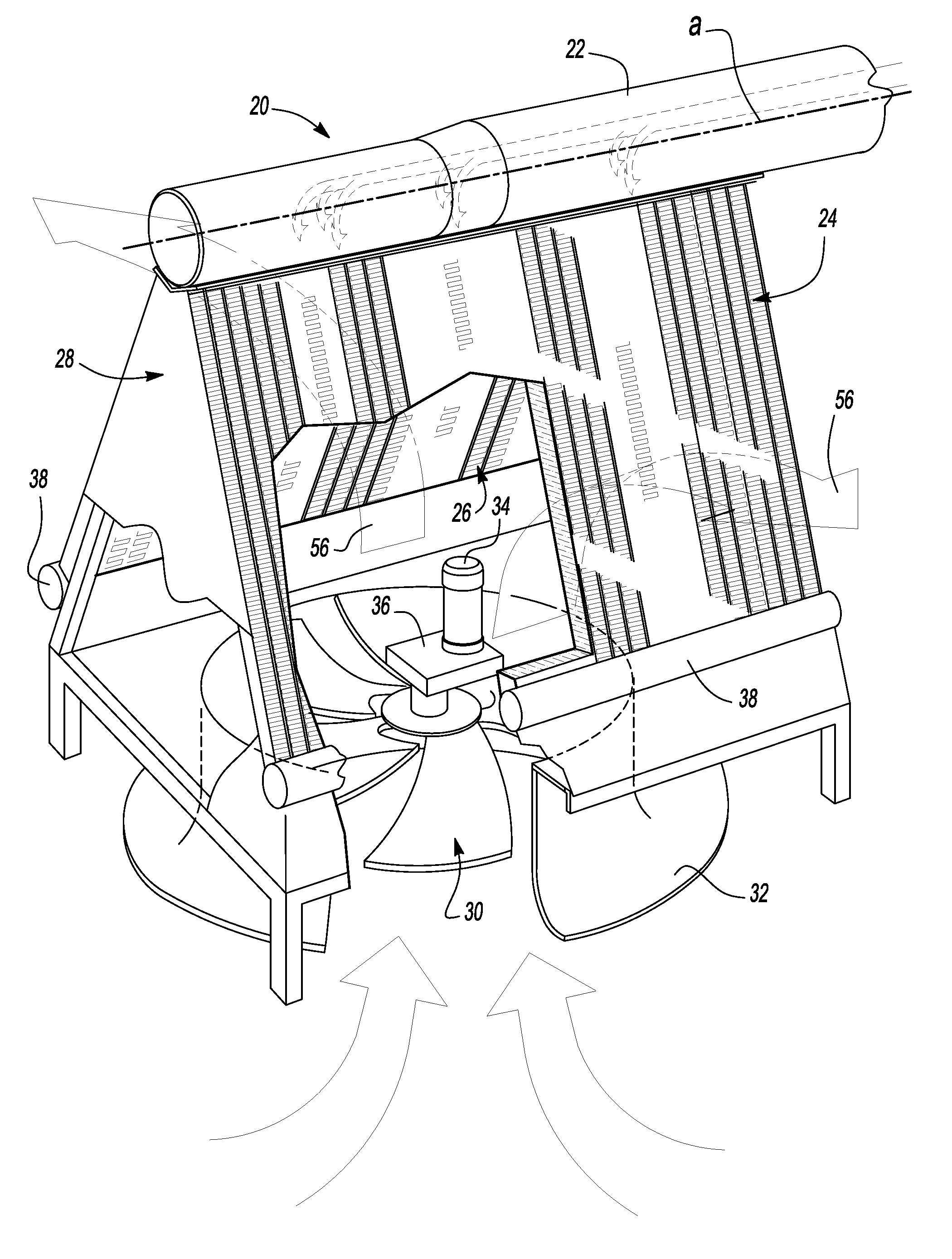
[0013]As set forth above, the air cooled steam condenser of this invention is particularly, but not exclusively adapted to condense steam from the exhaust of a steam turbine. A steam turbine is a mechanical device that extracts thermal energy from pressurized steam and converts it to rotary shaft motion. Steam turbines have been used commercially for over 100 years and are particularly suited to be used to drive an electric power generator. About 80% of all electricity generated in the world is by use of steam turbines. Air cooled steam condenser systems are commonly used in various industries as set forth above. However, there are limits in the overall efficiency of current turbine exhaust steam condensers due to the higher pressure drops experienced at low turbine back pressure. Further, air-cooled steam condensers for condensing steam from a steam turbine also accumulate corrosive non-condensable gases, such as carbon dioxide and air. Such trapped gases can corrode the inside sur...


PUM

PropertyMeasurementUnit
heightaaaaaaaaaa
thicknessaaaaaaaaaa
thicknessaaaaaaaaaa

Abstract

An air cooled steam condenser for condensing exhaust steam from a steam turbine including a steam delivery manifold, first and second bundles of aligned elongated tubes extending downwardly at an angle to the axis of the steam delivery manifold, each bundle containing a plurality of elongated tubes having exterior aluminum fins, an exterior coating of aluminum and an interior cladding of stainless steel having a thickness between about 45 and 125 microns, wherein a height measured between the rounded ends of the tubes is greater than 220 mm or between 220 and 280 mm and the length of the tubes is greater than 11 m, preferably between 12 and 14 m or greater.

Description

RELATED APPLICATIONS[0001]This application claims priority to U.S. Provisional Patent Application Ser. No. 61 / 170,839, filed Apr. 20, 2009.FIELD OF THE INVENTION[0002]This invention relates to an air-cooled steam condenser for turbines having improved efficiency. More specifically, this invention relates to turbine exhaust condensers having banks of aligned elongated tubes receiving steam from the turbine exhaust and an axial fan or fans directing ambient air over the tube banks.BACKGROUND OF THE INVENTION[0003]Steam turbines, as invented in 1884, extract thermal energy from pressurized steam and convert the thermal energy into rotary motion of the turbine shaft. Steam condensing systems are commonly used in electric power generating plants, solar collectors, fossil fuel and nuclear reactors generating steam and other steam generating processes where steam turbines are used.[0004]The general configuration of an air-cooled steam condenser for a steam turbine as disclosed, for example...

Claims


Application Information

Patent Timeline
Patent Type & Authority Applications(United States)
IPC IPC(8): F28D1/047F01K9/00
CPCF28B1/06F28F1/126F28F2225/04F28F21/089F28F2245/00F28F19/06
Inventor NOBEL, ARIE M.
Owner RES COTTRELL DRY COOLING
Why Eureka
Try Eureka