Dumbbell with adjustable weight

Active Publication Date: 2021-09-16
YIH AN EXNT
View PDF0 Cites 0 Cited by
  • Summary
  • Abstract
  • Description
  • Claims
  • Application Information

AI Technical Summary

Benefits of technology

The invention is a dumbbell that is simple to adjust the weight of. The technical effect of the invention is to make it easy and convenient for users to adjust the weight of a dumbbell.

Problems solved by technology

However, to adjust the weight of the conventional dumbbell, the limiting elements have to be detached from the grip rod first.
Finally, the two limiting elements are attached to the grip rod again. therefore, to conventional dumbbell is trouble, time-consuming, and inconvenient in adjusting the weight.
In addition, the counterweight blocks have to be attached or removed from outside to inside and the attachment positions of the counterweight blocks cannot be chosen freely, so the variety of the counterweight way of the conventional dumbbell is not versatile.

Method used


Image

  • Dumbbell with adjustable weight
  • Dumbbell with adjustable weight
  • Dumbbell with adjustable weight

Examples


Embodiment Construction

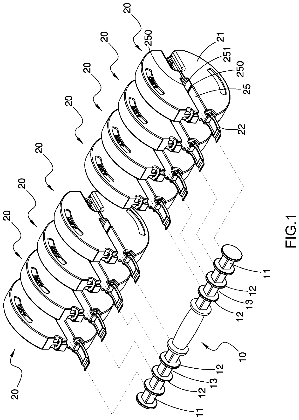
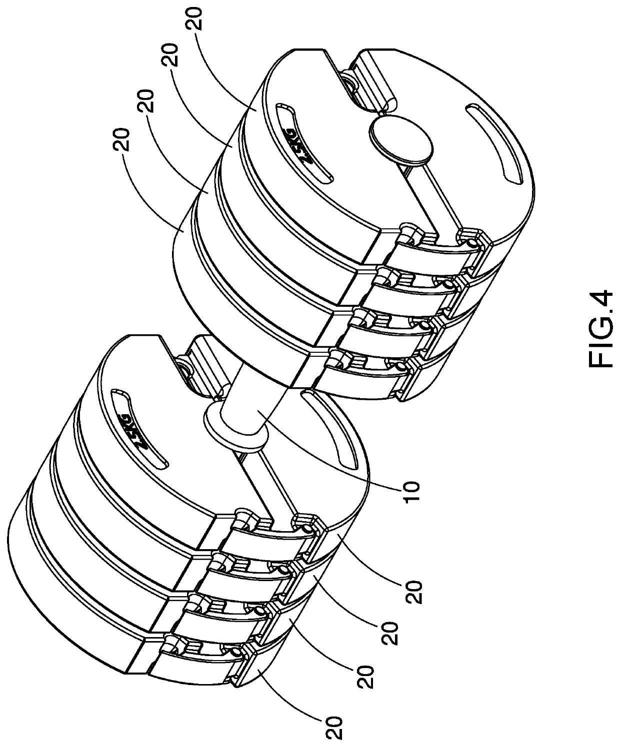
[0014]With reference to FIGS. 1 to 6, a dumbbell in accordance with the present invention comprises grip rod 10 and multiple counterweight blocks 20.

[0015]The grip rod 10 has two connection segments 11 formed respectively on two ends of the grip rod 10. Multiple baffles 12 are formed on each connection segment 11 at spaced interval to define multiple connection recesses 13 between the baffles 12.

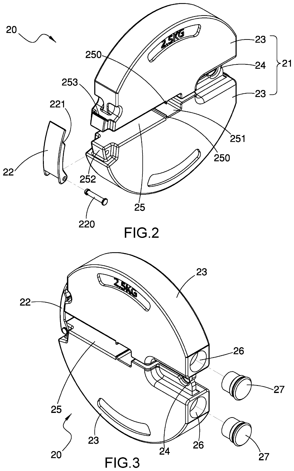
[0016]The counterweight blocks 20 are engaged respectively with the connection recesses 13 in the two connection segments 11. Each counterweight block 20 comprises a body 21 and a buckle 22. The body 21 is formed of blow molding and comprises two halves 23 and a connection section 24 connected between the halves 23. each half 23 has a specific thickness and is hollow. an engaging channel 25 is formed in the body 21 and extends from a center a center of the body 21 to an edge of the body 21, and the engaging channel 25 has an opening opposite the connection section 24 and is expandable from t...


PUM


Abstract

A dumbbell has a grip rod and multiple counterweight blocks. The grip rod has two connection segments each having multiple baffles to define multiple connection recesses between the baffles. The counterweight blocks are engaged respectively with the connection recesses. Each counterweight block has a body and a buckle. The body has an engaging channel extending from a center to an edge of the body and being expandable. The engaging channel has an opening and two protrusions to form an engaging space for being mounted around one of the connection segments. The buckle has a first end and a second end. The first end is connected pivotally to the body and at a position on one of two sides of the engaging channel. The second end is connected detachably with the body at a position on the other one of the two sides of the engaging channel.

Description

BACKGROUND OF THE INVENTION1. Field of the Invention[0001]The present invention relates to an exercising device, and more particularly to a dumbbell that is easy, rapid and convenient in weight-adjusting.2. Description of Related Art[0002]A conventional dumbbell with an adjustable weight substantially comprises a grip rod and multiple counterweight blocks mounted around two ends of the grip rod. Each counterweight block has a round hole defined in a center of the counterweight block. Two limiting elements are mounted on the grip rod respectively at positions adjacent to the outermost two of the counterweight blocks to hold the counterweight blocks on the grip rod.[0003]However, to adjust the weight of the conventional dumbbell, the limiting elements have to be detached from the grip rod first. Then, the counterweight blocks should be removed from the outermost ones or new counterweight blocks should be attached to the grip rod from two ends of the grip rod. Finally, the two limiting...

Claims


Application Information

Patent Timeline
IPC IPC(8): A63B21/072
CPCA63B21/0728A63B21/0726A63B21/075A63B21/0603A63B21/0602
Inventor CHIANG, CHIEH-LUNG
Owner YIH AN EXNT
Why Eureka
Try Eureka