Eureka AIR delivers breakthrough ideas for toughest innovation challenges, trusted by R&D personnel around the world.

Tourniquet device

Active Publication Date: 2022-02-10
DE XING MEDICAL TREATMENT & INSTR CO LTD
View PDF0 Cites 1 Cited by
  • Summary
  • Abstract
  • Description
  • Claims
  • Application Information

AI Technical Summary

Benefits of technology

The tourniquet device is a tool used to stop bleeding from wounds. It is applied by positioning a pressure plate on the limb between the wound and the heart, and then tightening a strap around the limb to bring the pressure plate close to the wound. The device uses a dial to engage a control rod, which, through ratchets, pulls a tightening band around the strap to further tighten it and stops bleeding. A locking rod prevents the control rod and winding rod from being turned back and keeps the strap tightened. The technical effect of the tourniquet device is to provide a simple and effective way to stop bleeding from wounds.

Problems solved by technology

The assembly of the combat tourniquet is therefore rather inconvenient.
Especially, the first strap and second strap are twisted and the smoothness of their fastening is compromised.
As such, the first strap or second strap is often stuck in a flurry during an emergency, endangering the life of the wounded.
Furthermore, the twisting rod cannot be fixed during its application and the first strap and second strap are loosed once the twisting rod is not held firmly, thereby failing to stanch bleeding.

Method used


Image

  • Tourniquet device
  • Tourniquet device
  • Tourniquet device

Examples


Embodiment Construction

[0019]The following descriptions are exemplary embodiments only, and are not intended to limit the scope, applicability or configuration of the invention in any way. Rather, the following description provides a convenient illustration for implementing exemplary embodiments of the invention. Various changes to the described embodiments may be made in the function and arrangement of the elements described without departing from the scope of the invention as set forth in the appended claims.

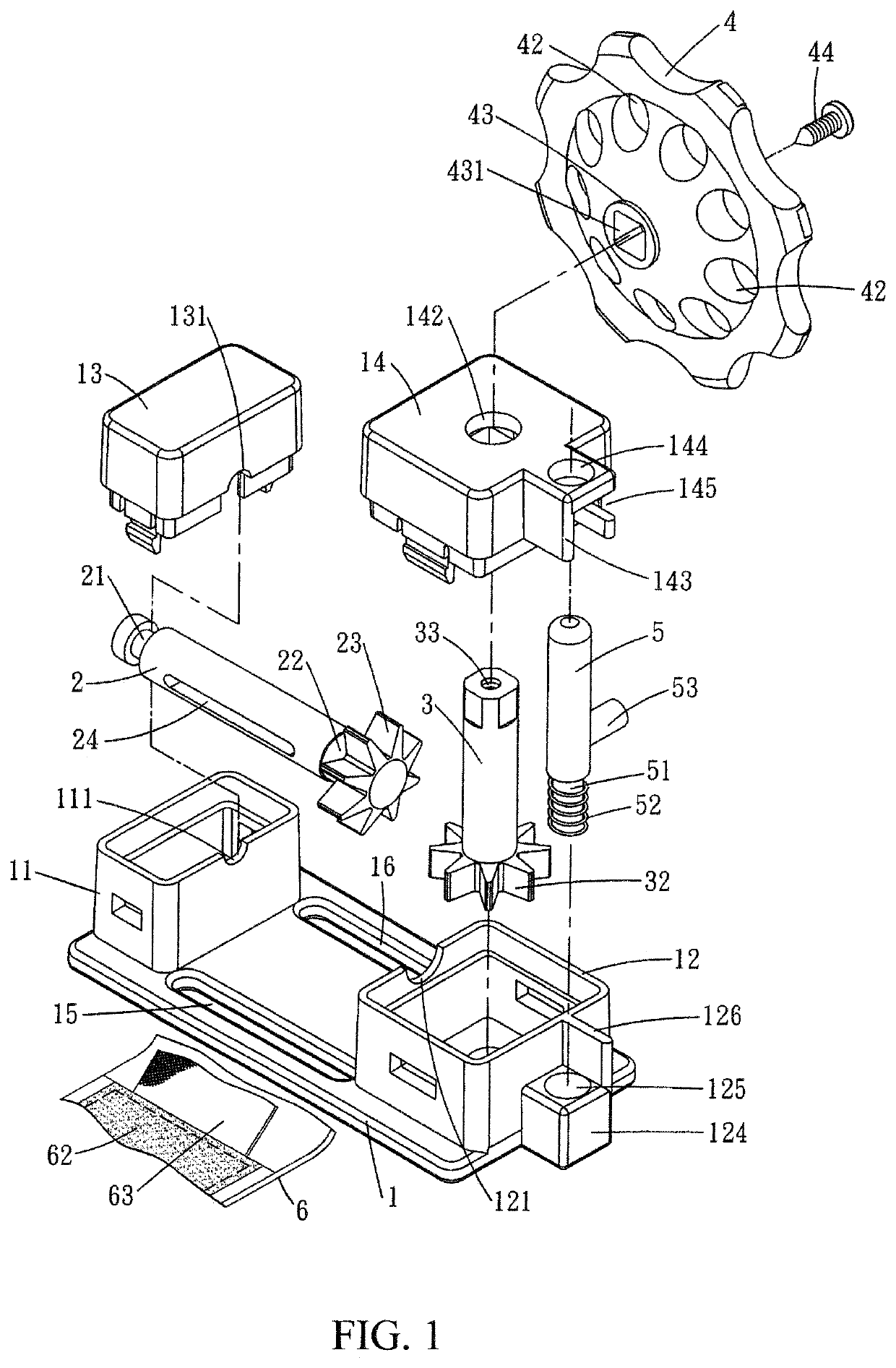
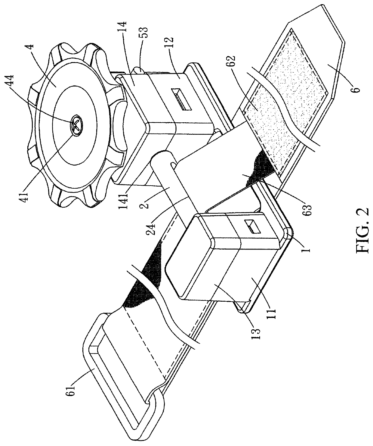
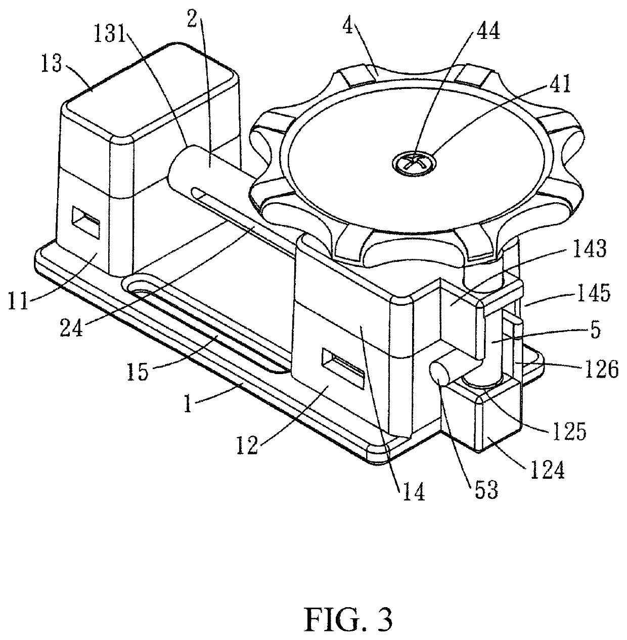
[0020]As shown in FIG. 1 and FIG. 2, a tourniquet device according to an embodiment of the present invention includes a pressure plate 1, a winding rod 2, a control rod 3, a dial 4, a locking rod 5, and a strap 6.

[0021]As shown in FIG. 3 and FIG. 4, the pressure plate 1 has an integrally formed body with a planar bottom surface for placing flatly on the surface of a patient's limb. A first case 11 and a second case 12 are respectively provided on two ends of a top surface of the pressure plate 1. Bo...


PUM


Abstract

The tourniquet device includes a pressure plate, a winding rod, a control rod, a dial, a locking rod, and a strap. The winding rod and has a ratchet at one end. A ratchet is provided around a bottom end of the control rod engaging the ratchet of the winding rod. The dial is fixedly joined to the control rod, and locking holes are provided on the bottom side of the dial. The locking rod is for locking the dial. The strap has a first end fixedly connected to a buckle and a second end threaded through the slits of the pressure plate and then through the buckle and back. A fastener patch is attached to the strap, and a tightening band has a first end fixedly joined to the strap between the buckle and the fastener patch and a second end is threaded through the slit of the winding rod.

Description

BACKGROUND OF THE INVENTION(a) Technical Field of the Invention[0001]The present invention is generally related to tourniquets, and more particular to pressurized tourniquet device.(b) Description of the Prior Art[0002]Conventional tourniquets usually involve a strap wrapping around a limb between a wound and the heart for applying pressure to stop bleeding.[0003]These conventional tourniquets are usually effective to smaller wounds, but not to larger wounds.[0004]There are so called combat tourniquets that are applicable to larger wounds and more severe bleeding. One example is Taiwan Patent No. M551906 whose teaching includes a plate, a twisting rod, a first strap, and a second strap. The first strap is wrapped around a limb between the wound and the heart and fastened to preliminarily stanch bleeding. The twisting rod is then engaged to pull the first strap and second strap and a locking element fixes the twisting rod to additionally stanch bleeding. The first strap and second st...

Claims


Application Information

Patent Timeline
IPC IPC(8): A61B17/132
CPCA61B17/1327A61B2017/00367A61B17/1325
Inventor HSIAO, TE-HSIN
Owner DE XING MEDICAL TREATMENT & INSTR CO LTD
Why Eureka
Eureka Blog
Learn More