High Current Component

a high-current component and functional technology, applied in the direction of printed circuit aspects, electrical equipment, instruments, etc., can solve the problems of high risk of failure, and certain soldering effort required in manufacturing, and achieve the effect of expanding existing circuits

Pending Publication Date: 2022-03-24
NACHSEL ROMAN
View PDF6 Cites 0 Cited by
  • Summary
  • Abstract
  • Description
  • Claims
  • Application Information

AI Technical Summary

Benefits of technology

[0041]Such an alternative enables, for example, the measuring of phase related properties of current and voltage or other physical measuring values in a multi-phase alternating current circuit. A voltage source for the functional electronics can be provided, for example, by occurring potential differences between the individual phases. Such an alternative enables the use of advantages of the presence of several high current potentials or signals which must be considered in relation to each other and the possible expandability of existing circuits.

Problems solved by technology

This means, that a certain soldering effort is necessary during manufacturing.
Each solder joint has a failure probability.
The more parts that are used, the higher is the risk of failure.
Thereby, known assemblies and their functional design is complex.
This is expensive and costs a lot of time and it requires much competence of the responsible staff.

Method used


Image

  • High Current Component
  • High Current Component
  • High Current Component

Examples


first embodiment

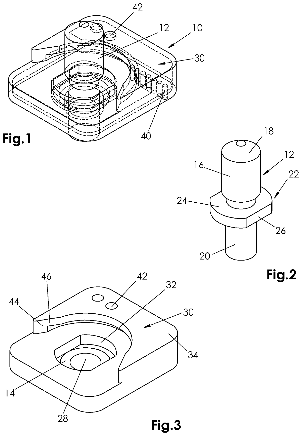
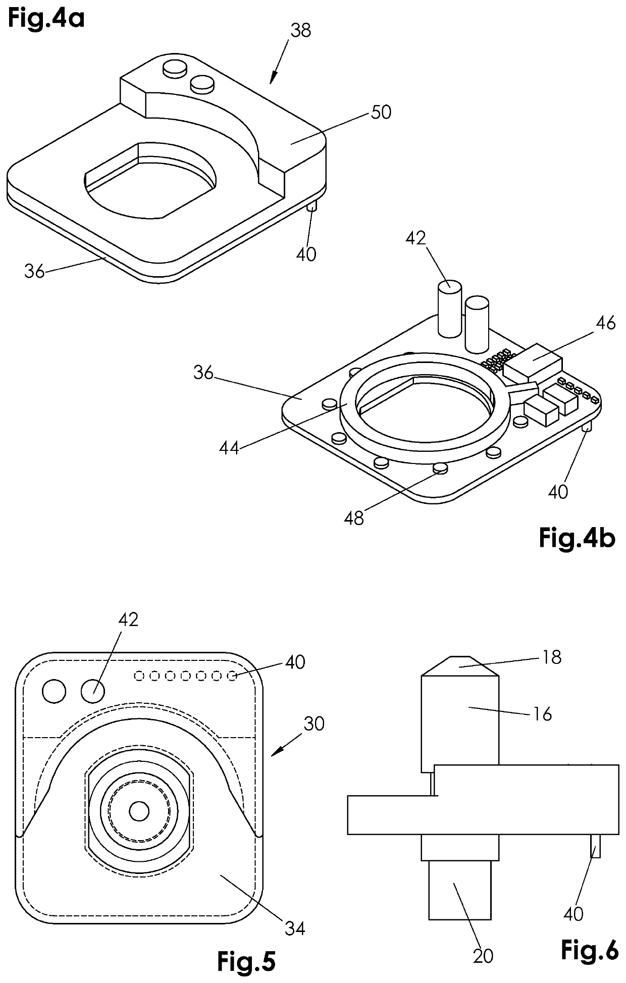
[0065]FIG. 1 to FIG. 6 show a high current component generally designated with numeral 10. The high current component 10 is built-on modular. A first module is formed by a commercially available contact adapter 12. This is shown in FIG. 2. The contact adapter 12 sits in a press-fit component 14. The press-fit component is annular and can be recognized in FIG. 3. Such contact adapters 12 and press-fit components 14 are disclosed, for example, on the sites https: / / powerelement.we-online.de / products and https: / / hdm-innowema.de / f / tk_tacksert_pins.pdf. It is understood that the shown contact adapter 12 and the press-fit component 14 may vary with respect to its form and material and are shown here by way of example only. Alternatively the press-fit component can be individually inserted.

[0066]The contact adapter 12 is provided with a cylindrical contact 16 at its upper end in FIG. 2. The upside 18 of the contact is conically shaped. A conductor or the like can be connected to the contact...

second embodiment

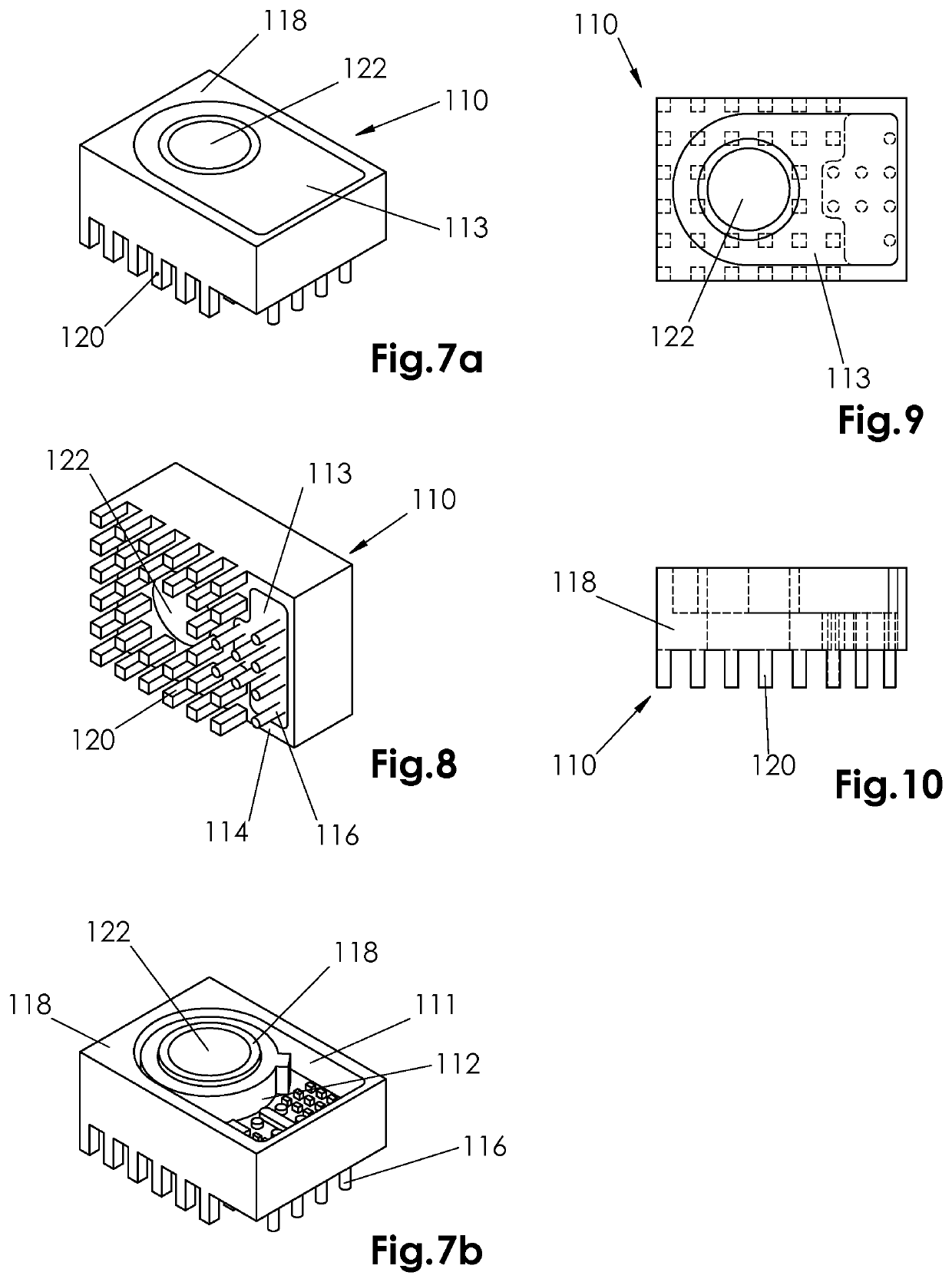
[0074]FIG. 7 to FIG. 10 show a high current component generally designated with numeral 110 with a metal body 118. Known high current press-fit pins form an integral part of the metal body 118. It is understood, that any other fixing- and contacting form is also suitable. A through bore 122 serves to contact a high current connector, such as an electric cable.

[0075]The high current component 110 differs from the known high current components in so far as it is provided with a cutout 111 which accommodates a functional electronics 112. This can be recognized in FIG. 7b. The cutout 111 partly extends to the bottom of the high current component 110 and extends around the through bore 122. The installations space provided for the functional electronics 112 is designated with numeral 113 in FIG. 7a.

[0076]FIG. 8 shows the underside 114 of the functional electronics 112 with the corresponding contacts 116 and 120. Contacts 120 serve to establish contact with the printed circuit board. As ...

embodiment 3 (fig.11)

Embodiment 3 (FIG. 11)

[0078]A portion of a printed circuit board 124 is shown in FIG. 11. The printed circuit board 124 is provided with tracks 126 and conductive areas 128 in the usual way. The conductive area 128 shown by way of example, is designed, by way of example, as a high current conductive area of NiAu- (ENIG, ENEPIG) coated copper. It is understood that different suitable materials may also be used. In the present embodiment the tracks on the printed circuit board 124 serve as signal- and reference potential lines.

[0079]Electric high current contacts 130 are provided on the conductive area 128. A high current component is press-fitted with its contact pins into such electric contacts 130 from below. In addition to the high current contacts the high current component has electrical contacts 131 which, in particular, may be designed as Skedd-contacts. This is exemplary illustrated in FIG. 12. The contacts 131 are provided for signals and reference potentials. In the present...


PUM


Abstract

A functional electronics unit for a high current component which is provided for electrical and mechanical connection to a circuit board or to another mechanical carrier substrate for a circuit grouping or circuit, with conductor tracks, conductive surface elements and/or other conductive regions and contacts, the functional electronics unit having electronic components which are designed to measure properties of the electric current flowing through the component or of an electric voltage applied to the component or to perform another electronic functionality, is characterized in that the functional electronics unit is retained on the high current component or on a common carrier. More particularly, the functional electronics unit can be integrated into the high current components and/or can be pushed onto the high current component in a modular fashion or can be fixed on the high current component.

Description

TECHNICAL FIELD[0001]The invention relates to a functional electronics for a high current component which is provided for electrically and mechanically connecting to a printed circuit board or another mechanic carrier substrate for a circuitry or a circuit having conductive paths, conductive area elements and / or other conductive ranges and contacts which are designed for high currents wherein the functional electronics is provided with electronic parts which are suitable for measuring the properties of the electric current flowing through the component or an electric voltage applied to the component or for carrying out another electronic functionality.[0002]Furthermore, the invention relates to a high current component for electrically and mechanically connecting to a printed circuit board or another mechanic carrier substrate for a circuitry or a circuit having conductive paths, conductive area elements and / or other conductive ranges and contacts which are designed for high current...

Claims


Application Information

Patent Timeline
Patent Type & Authority Applications(United States)
IPC IPC(8): G01R15/14H05K1/02
CPCG01R15/148H05K2201/10106H05K1/0274H05K1/0263G01R15/18H05K1/0254H05K1/0265H05K1/0268H05K3/325H05K2201/09063H05K2201/10121H05K2201/10189H05K2201/10424
Inventor NACHSEL, ROMAN
Owner NACHSEL ROMAN
Why Eureka
Try Eureka