Al technical title is built by PatSnap Al team. It summarizes the technical point description of the patent document.
a tissue ablation and cavitation technology, applied in the field of medical devices, can solve the problems of abnormal or potentially cancerous cells that the surgeon fails, or is unable, to excise, and achieve the effect of less wattag
Pending Publication Date: 2022-04-28
INNOBLATIVE DESIGNS INC
View PDF0 Cites 0 Cited by
Summary
Abstract
Description
Claims
Application Information
AI Technical Summary
This helps you quickly interpret patents by identifying the three key elements:
Problems solved by technology
Method used
Benefits of technology
[0007]The tissue ablation system of the present disclosure can be used during an ablation procedure to destroy the thin rim of marginal tissue around the cavity in an effort to manage residual disease in the local environment that has been treated. In particular, the present disclosure is generally directed to a cavitary tissue ablation system including an ablation device to be delivered into a tissue cavity and emit non-ionizing radiation, such as radiofrequency (RF) energy, to treat the marginal tissue around the tissue cavity. The ablation device generally includes a probe having a deployable applicator member or head coupled thereto and configured to transition between a collapsed configuration, in which the applicator head can be delivered to and maneuvered within a previously formed tissue cavity (e.g., formed from tumor removal), and an expanded configuration, in which the applicator head is configured to ablate marginal tissue (via RF) immediately surrounding the site of a surgically removed tumor in order to minimize recurrence of the tumor. The tissue ablation device of the present disclosure is configured to allow surgeons, or other medical professionals, to deliver precise, measured doses of RF energy at controlled depths to the marginal tissue surrounding the cavity.
[0019]The dual-balloon design is particularly advantageous in that it does not require a syringe pump, and can be supplied with gravity-fed fluid source. In addition, the volume of fluid required within the chamber is significantly less (when compared to a single balloon design), thus less wattage is required to achieve RF ablation.
Problems solved by technology
However, after the tumor is destroyed, a hollow, irregularly-shaped cavity may remain, wherein tissue surrounding this cavity and surrounding the original tumor site can still leave abnormal or potentially cancerous cells that the surgeon fails, or is unable, to excise.
Method used
Image
Click on the blue label to locate the original text in one second.
Reading with bidirectional positioning of images and text.
Examples
Embodiment Construction
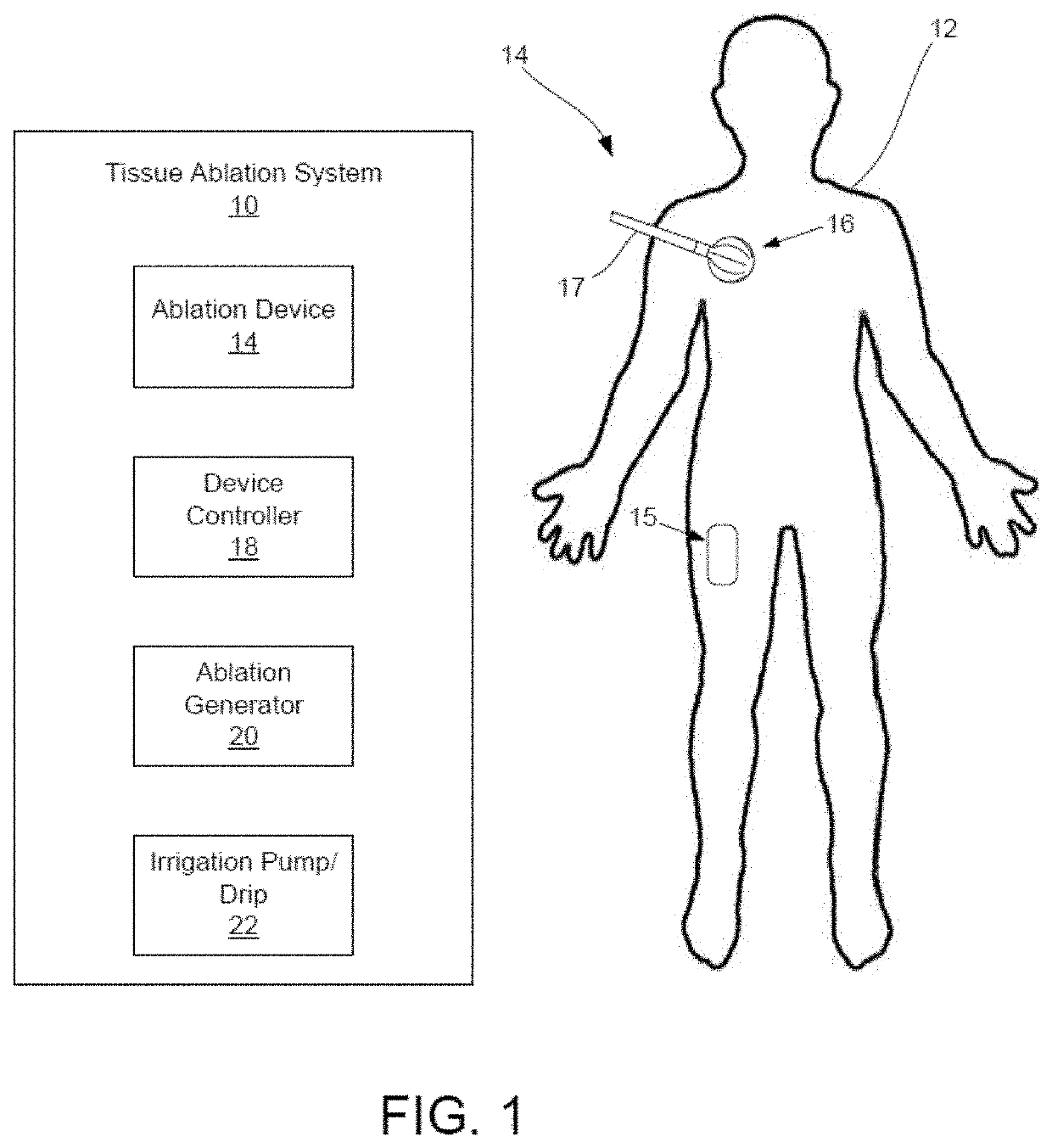
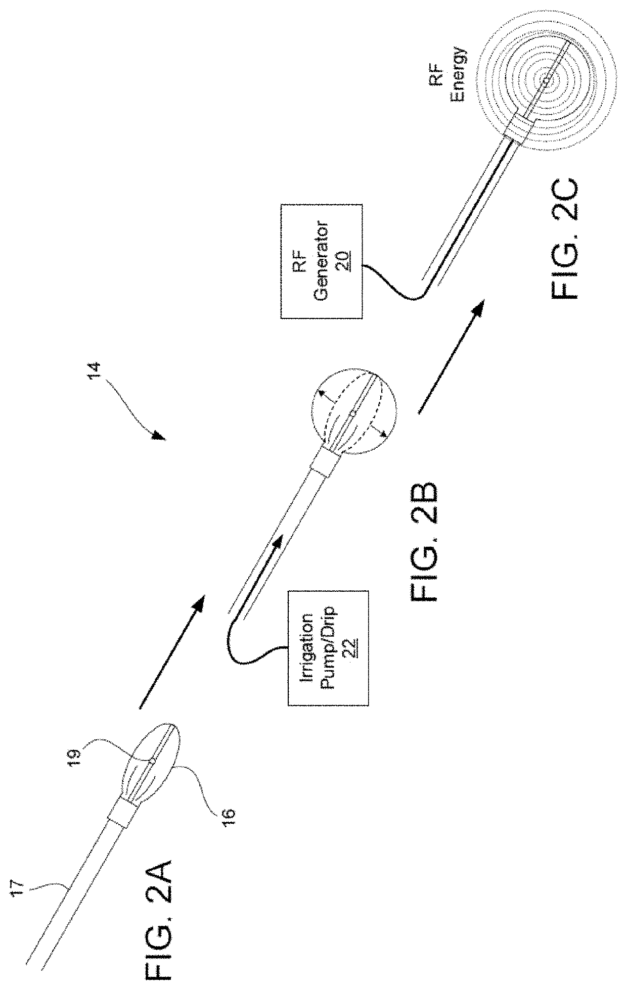
[0046]By way of overview, the present disclosure is generally directed to a tissue ablation device having a deployable applicator head configured to be delivered into a tissue cavity and ablate marginal tissue surrounding the tissue cavity. In preferred aspects, the tissue ablation device of the invention includes a probe having a deployable applicator member or head that has a non-spherical shape when in its expanded configuration. The applicator member or head may have, as non-limiting exemplary embodiments, an ellipsoid, conical, cylindrical, or polyhedron shape.
[0047]A tissue ablation system consistent with the present disclosure may be well suited for treating hollow body cavities, such as irregularly-shaped cavities in breast tissue created by a lumpectomy procedure. For example, once a tumor has been removed, a tissue cavity remains. The tissue surrounding this cavity is the location within a patient where a reoccurrence of the tumor may most likely occur. Consequently, after...
PUM
Abstract
The invention relates to a tissue ablation system including an ablation device having a deployable applicator, preferably, with a non-spherical head configured to be delivered to a tissue cavity and ablate marginal tissue surrounding the tissue cavity. The deployable applicator head is configured to be delivered to a tissue cavity while in a collapsed configuration and ablate marginal tissue surrounding the tissue cavity while in an expanded configuration.
Description
CROSS-REFERENCE TO RELATED APPLICATIONS[0001]This application claims the benefit of, and priority to, U.S. Provisional Application No. 63 / 133,944, filed Jan. 5, 2021, the contents of which are herein incorporated by reference in their entirety.[0002]This application is a continuation-in-part of U.S. application Ser. No. 16 / 422,264, filed May 24, 2019, which is a continuation of U.S. application Ser. No. 15 / 142,616, filed Apr. 29, 2016 (now issued as U.S. Pat. No. 10,342,611), which claims the benefit of, and priority to, U.S. Provisional Application No. 62 / 154,377, filed Apr. 29, 2015, the contents of which are herein incorporated by reference in their entirety.FIELD OF THE INVENTION[0003]The present disclosure relates generally to medical devices, and, more particularly, to a tissue ablation device having a deployable applicator head configured to be delivered to a tissue cavity and ablate marginal tissue surrounding the tissue cavity.BACKGROUND[0004]Cancer is a group of diseases i...
Claims
Application Information
Patent Timeline
Application Date:The date an application was filed.
Publication Date:The date a patent or application was officially published.
First Publication Date:The earliest publication date of a patent with the same application number.
Issue Date:Publication date of the patent grant document.
PCT Entry Date:The Entry date of PCT National Phase.
Estimated Expiry Date:The statutory expiry date of a patent right according to the Patent Law, and it is the longest term of protection that the patent right can achieve without the termination of the patent right due to other reasons(Term extension factor has been taken into account ).
Invalid Date:Actual expiry date is based on effective date or publication date of legal transaction data of invalid patent.
Patent Type & Authority Applications(United States)