Data storage system having an optical processing flying head

a data storage system and flying head technology, applied in the field of data storage systems having optical data tracking, storage and retrieval systems, can solve the problems of insufficient physical size of the head the volumetric storage capacity of the mo disk drive generally not keeping pace with the volumetric storage capacity of the magnetic disk drive, and the limited history of the winchester magnetic hard disk technology

Inactive Publication Date: 2000-03-07
SEAGATE TECH LLC
View PDF74 Cites 35 Cited by
  • Summary
  • Abstract
  • Description
  • Claims
  • Application Information

AI Technical Summary

Problems solved by technology

Winchester magnetic hard disk technology has historically been limited by at least two factors, including: magnetic head design and the magnetic storage media.
However, despite the historically higher areal storage density available for use with magneto-optical disks drives, the prior art MO disk drive volumetric storage capacity has generally not kept pace with the volumetric storage capacity of magnetic disk drives.
One factor limiting MO disk drives has been the physical size of the head necessary to hold the various components required for accessing magneto-optical information.
In the prior art, the large physical size of MO flying heads also limits the spacing between magneto-optical disks to a finite minimum value and, therefore, limits the volumetric storage capacity which may be achieved.
This design limits the tracking servo bandwidth and achievable track density due to its size and weight.
Its complexity also increases the cost and difficulty of manufacture.
The size and mass of the mirror limited higher operating frequency.
Also, mirror distortion caused by the high dynamic torque (i.e. peak angular acceleration ) at higher frequency was a limiting factor.
The noise limits the achievable data rate at a given signal level.
Any residual birefringent characteristic of an optical fiber will reduce signal detection sensitivity.

Method used


Image

  • Data storage system having an optical processing flying head
  • Data storage system having an optical processing flying head
  • Data storage system having an optical processing flying head

Examples


Embodiment Construction

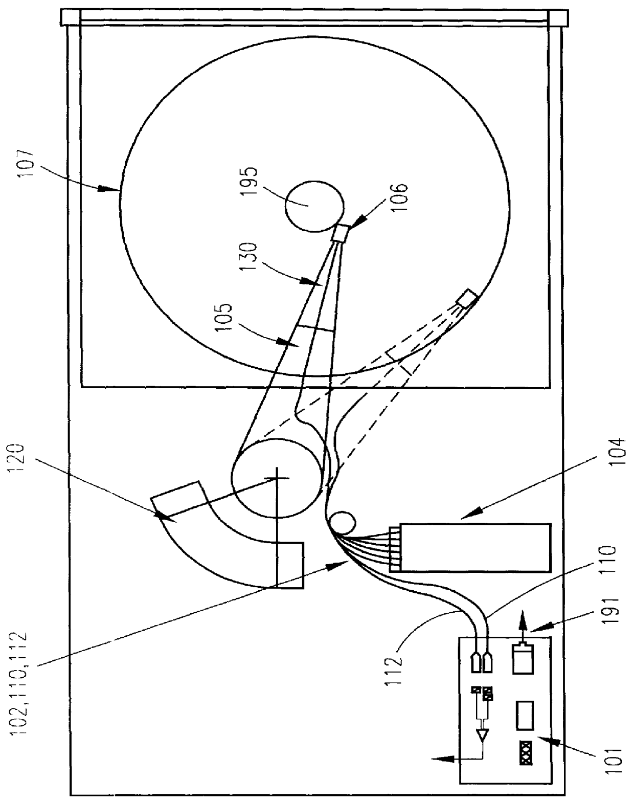
Referring in detail now to the drawings wherein similar parts of the invention are identified by like reference numerals, there is seen in FIG. 1 a diagram showing a magneto-optical data storage and retrieval system. In an exemplary embodiment, magneto-optical (MO) data storage and retrieval system 100 includes a set of Winchester-type flying heads 106 that are adapted for use with a set of double-sided first surface MO disks 107 (only one disk and one head shown). The set of flying heads 106 (hereinafter referred to as flying MO heads) are coupled to a rotary actuator magnet and coil assembly 120 by a respective suspension 130 and actuator arm 105 so as to be positioned over the surfaces of the set of MO disks 107. In operation, the set of MO disks 107 are rotated by a spindle motor 195 so as to generate aerodynamic lift forces between the set of MO heads 106 and so as to maintain the set of MO heads 106 in a flying condition approximately 15 micro-inches above the upper and lower ...


PUM

PropertyMeasurementUnit
diameteraaaaaaaaaa
thickaaaaaaaaaa
resonant operating frequencyaaaaaaaaaa

Abstract

An optical data storage and retrieval system uses a flying head. The flying head is supported on a moving media having information stored in a plurality of stored data locations thereon. Information is stored in each of the plurality of media locations as physical structures capable of modulating the polarization state of incident light into one of two output polarization states. The flying head includes an optical processing assembly which directs an incident light beam having a source polarization state onto the moving media, accessing successive data locations. A reflected light beam having the source polarization state of the incident light beam modulated by a respective polarization modifying data location into one of the output polarization states is received by the flying head. The optical processing assembly optically transforms the modulated output polarization state of the reflected light beam into two return light beams having differentially modulated intensity related to the output polarization state of the reflected light beam. The two intensity modulated return light beams are optically coupled to a distal differential detector which outputs digital data representing the stored data information for the subject data location. A preferred embodiment includes optical fibers for coupling the incident and return light beams between the detector and the flying head. The optical assembly of a preferred embodiment includes an optical plate having pre-shaped and dimensioned recesses for automatically locating and aligning multiple optical components comprising the assembly. The flying head may also include a servo-controlled micro machined mirror for directing the incident and reflected light beams to and from the media.

Description

1. Field of the InventionThe present invention relates generally to data storage systems having optical data tracking, storage and retrieval systems. More particularly, the present invention relates to data storage, tracking, and retrieval systems that include optics.2. Background ArtIn data recording and retrieval systems, using a moving media having a varying material characteristic, detectable variations from previously encoded media locations may be retrieved using incident light reflected from the media. Such variations may also be used in providing servo control signals for following previously recorded data tracks.In a magneto-optical storage system, using a magneto-optical (MO) recording material deposited on a rotating disk, information may be recorded on the disk as spatial variations of magnetic domains. During readout, the magnetic domain pattern modulates an optical polarization, and a detection system converts a resulting signal from optical to electronic format.In one...

Claims


Application Information

Patent Timeline
Patent Type & Authority Patents(United States)
IPC IPC(8): G02B26/08G02B6/35G02B6/42G02B6/126G11B7/22G11B11/105G11B11/00G11B7/12G11B7/085G11B7/125G11B7/135H02N1/00H04B10/135G02B6/10G11B7/00G11B7/14G11B7/09G11B7/0037
CPCG02B6/126G02B6/4246G02B26/0833G02B26/0841G02B26/0866G11B7/08564G11B7/1203G11B7/122G11B7/127G11B7/135G11B7/1362G11B7/1365G11B7/1372G11B7/1384G11B7/22G11B11/10532G11B11/10534G11B11/10541G11B11/10543G11B11/1058G11B11/10595H02N1/008H04B10/2572G02B6/105G11B7/0037G11B7/08576G11B7/0901G11B7/14G11B11/10515G11B11/10554G11B11/10563G11B11/10569
Inventor HEANUE, JOHN FWILDE, JEFFREY P.HURST, JR., JERRY E.JERMAN, JOHN H.
Owner SEAGATE TECH LLC
Why Eureka
Try Eureka