Utility meter and display system

a utility meter and display system technology, applied in the field of can solve the problem of not disclosing a new utility meter and display system, and achieve the effects of low manufacturing cost, convenient and efficient manufacturing and marketing, and durable and reliable construction

Inactive Publication Date: 2000-04-11
LERNER SAM
View PDF12 Cites 52 Cited by
  • Summary
  • Abstract
  • Description
  • Claims
  • Application Information

AI Technical Summary

Benefits of technology

It is another object of the present invention to provide a new Utility Meter and Display System which may be easily and efficiently manufactured and marketed.
It is a further object of the present invention to provide a new Utility Meter and Display System which is of a durable and reliable construction.
An even further object of the present invention is to provide a new Utility Meter and Display System which is susceptible of a low cost of manufacture with regard to both materials and labor, and which accordingly is then susceptible of low prices of sale to the consuming public, thereby making such Utility Meter and Display System economically available to the buying public.

Problems solved by technology

While these devices fulfill their respective, particular objectives and requirements, the aforementioned patents do not disclose a new Utility Meter and Display System.

Method used


Image

  • Utility meter and display system
  • Utility meter and display system
  • Utility meter and display system

Examples


Embodiment Construction

With reference now to the drawings, and in particular to FIGS. 1 through 6 thereof, a new Utility Meter and Display System embodying the principles and concepts of the present invention and generally designated by the reference numeral 10 will be described.

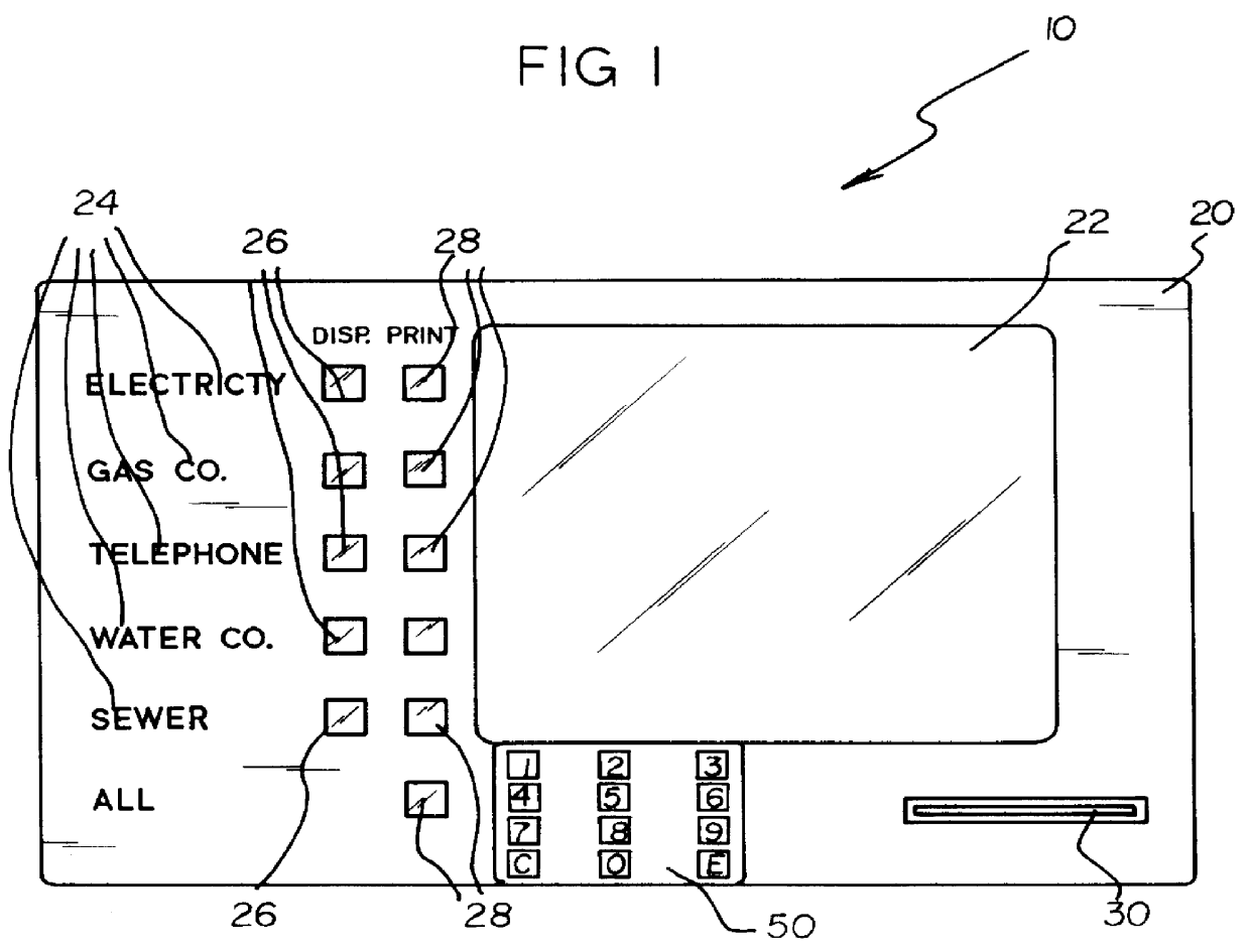
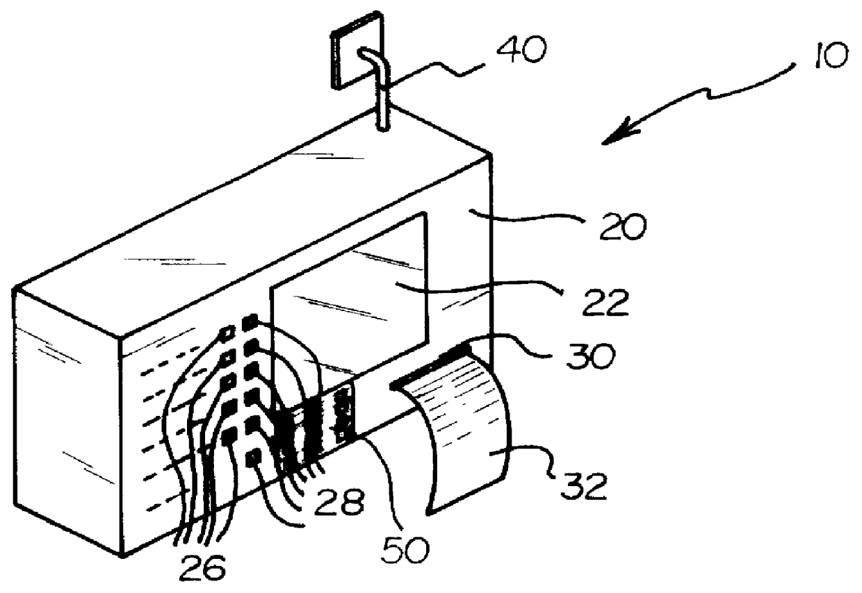
More specifically, it will be noted that the Utility Meter and Display System 10 comprises an encasement 20 having an interior, an unnumbered microprocessor, a display 22, a keypad 50, and a printer 30. The encasement 20 is preferably constructed for mounting to an interior wall of a building structure.

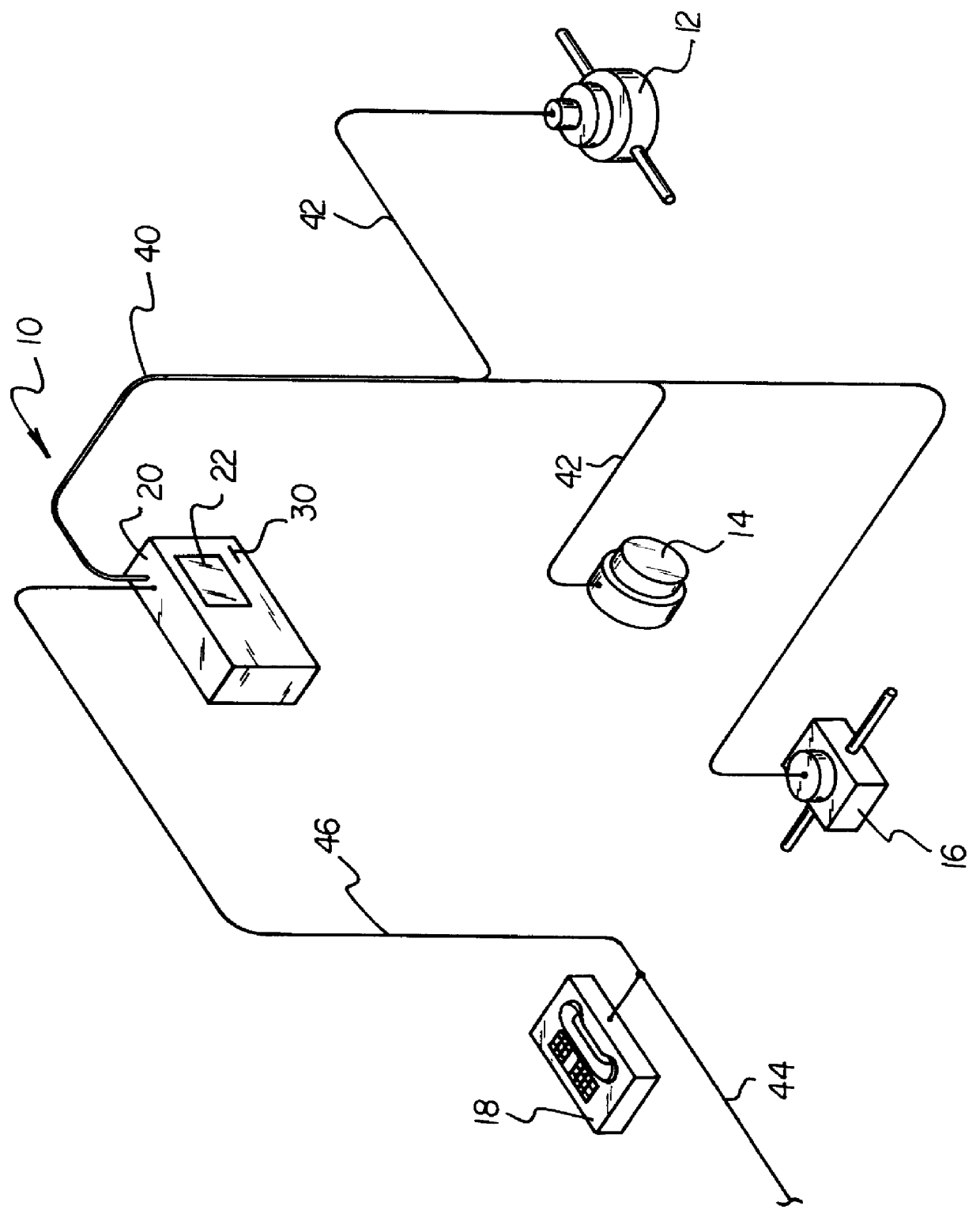
As shown in FIGS. 1 through 4 of the drawings, the display 22 is secured within the encasement 20 for displaying utility billing information from the unnumbered microprocessor. As shown in FIGS. 3 and 6 of the drawings, the unnumbered microprocessor is electrically connected to a water meter 12, an electric meter 14, a gas meter 16, and a telephone 18 for reading consumption data for each utility. A connecting phone cable 46 is elec...


PUM


Abstract

A new Utility Meter and Display System for reading and displaying utility usage information within a building structure. The inventive device includes an encasement, a microprocessor within the encasement, a display, a keypad, and a printer within the encasement for printing selected information for the user. The microprocessor is electronically connected to a water meter, an electric meter, a gas meter and a telephone for reading the usage of the various utilities. The printer is electronically connected to the microprocessor for printing out selected screens on the display. The inventive device preferably includes a modem within for receiving billing information from the utility companies for determining the current rates.

Description

BACKGROUND OF THE INVENTION1. Field of the InventionThe present invention relates to Utility Measuring Devices and more particularly pertains to a new Utility Meter and Display System for reading and displaying utility usage information within a building structure.2. Description of the Prior ArtThe use of Utility Measuring Devices is known in the prior art. More specifically, Utility Measuring Devices heretofore devised and utilized are known to consist basically of familiar, expected and obvious structural configurations, notwithstanding the myriad of designs encompassed by the crowded prior art which have been developed for the fulfillment of countless objectives and requirements.Known prior art Utility Measuring Devices include U.S. Pat. No. 5,214,587; U.S. Pat. No. 4,803,632; U.S. Design Pat. No. 357,426; U.S. Pat. No. 5,287,287; U.S. Pat. No. 5,153,837 and U.S. Pat. No. 4,449,187.While these devices fulfill their respective, particular objectives and requirements, the aforement...

Claims


Application Information

Patent Timeline
Patent Type & Authority Patents(United States)
IPC IPC(8): G07F15/00G06Q30/00G06Q30/04G06Q50/06
CPCG06Q30/04G07F15/00G06Q50/06
Inventor LERNER, SAM
Owner LERNER SAM
Why Eureka
Try Eureka