Fuel injection control device

Inactive Publication Date: 2000-06-20
ISUZU MOTORS LTD
View PDF10 Cites 34 Cited by
  • Summary
  • Abstract
  • Description
  • Claims
  • Application Information

AI Technical Summary

Problems solved by technology

The high fuel injection pressure, however, increases the fuel injection rate causing sudden combustion, which in turn results in increased engine noise.
But during the high load operation that requires large fuel flows, the fuel injection period in one combustion cycle becomes longer, rendering the sprayed fuel not easily atomizable, deteriorating both the engine output and the exhaust gas characteristics.
Designing the solenoid actuator in this way, however, results in driving the open-close valve with a large force provided for high common rail pressure even during the low load operation, such as idling, where the common rail pressure is set low.
This produces injector noise, which consists mainly of impact noise between the control rod, which functions as the armature of the solenoid, and the stopper that restricts the displacement of the armature.
During the low load operation such as idling, in particular, because

Method used


Image

  • Fuel injection control device
  • Fuel injection control device
  • Fuel injection control device

Examples


Embodiment Construction

An embodiment of this invention will be described by referring to the accompanying drawings.

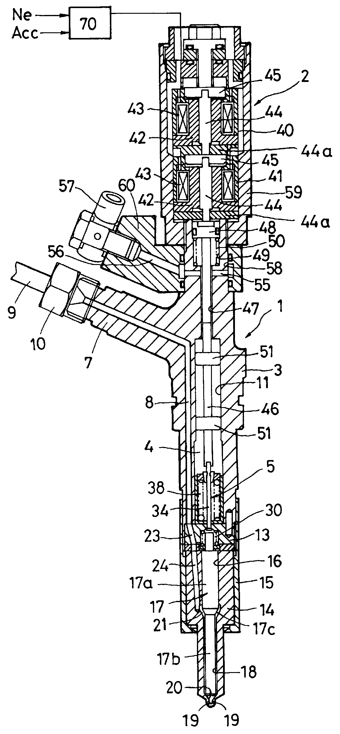
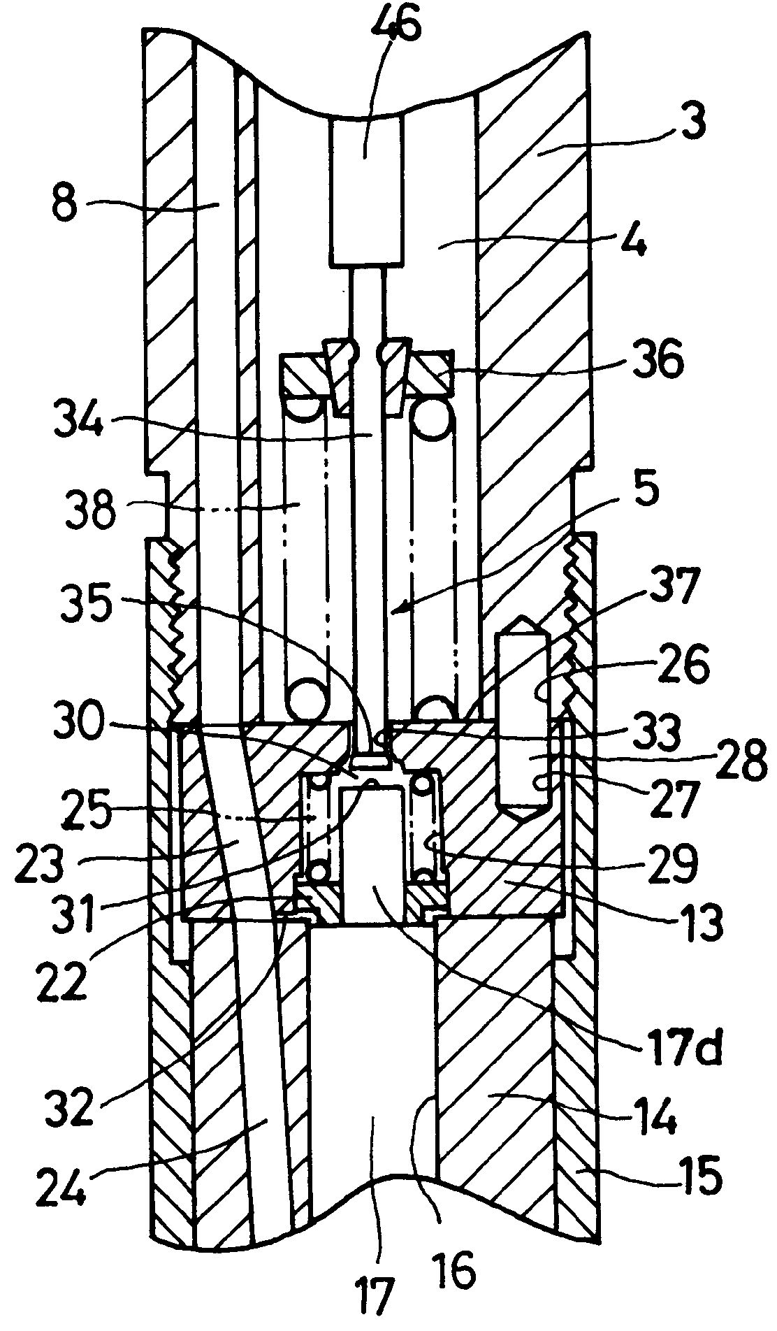
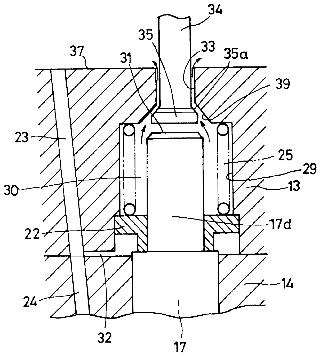
With reference to FIGS. 1, 2 and 3, one embodiment of an injector applying the fuel injection control device of this invention will be explained.

The injector is applied to a common rail injection system or an accumulator injection system (not shown). A high pressure fuel supplied through a common passage and a pressure accumulation chamber (not shown; hereinafter referred to as a "common rail") to which a fuel is supplied from a fuel injection pump is injected into individual combustion chambers in the engine by injectors. An injector body 1 has a solenoid actuator 2 provided on the base end side thereof to activate a needle valve 17 described later. The injector body 1 comprises a central portion 3 mounted to a bracket 60 as a fixing member such as an engine, a control portion 13, and a nozzle portion 14 that serves as a needle valve guide. The control portion 13 and the nozzle portion 14 ar...


PUM


Abstract

During the low load operation, this fuel injection control device reduces the initial armature displacement speed of the solenoid actuator that drives the open-close valve against the low fuel pressure in the balance chamber, thereby lowering impact noise produced in the solenoid portions. When the engine is determined to be idling, a command pulse width which energizes the solenoids of the solenoid actuator is calculated according to the target injection amount, the common rail pressure, and the target fuel injection timing. Since the initial period of the command pulse width, i.e., pull-in current conduction period, is set shorter than the pull-in current conduction period for the high load operation of the engine, the initial armature displacement speed of the solenoid becomes relatively slow reducing the impact noise of the armature abutting against the stopper.

Description

1. Field of the InventionThe present invention relates to a fuel injection control device applied to engines such as diesel engines and direct injection type gasoline engines.2. Description of the Prior ArtA fuel injection control device for engines such as diesel engines has been known, in which an open-close valve provided in a fuel discharge passage for releasing fuel in a balance chamber is opened and closed by a solenoid actuator to control a pressure in the balance chamber and thereby control the lift of a needle valve that receives the fuel pressure in the balance chamber, optimumly controlling the amount of fuel to be injected and the injection timing according to the operating conditions of the engine, such as engine revolution and load.The above fuel injection device has nozzle holes at the front end of the body for injecting fuel into the combustion chamber of the engine. A needle valve reciprocating in a hollow portion of the body opens and closes the nozzle holes with o...

Claims


Application Information

Patent Timeline
IPC IPC(8): F02M59/00F02M59/46F02D41/20F02M47/02F02D41/38F02M47/00F02M51/00F02M51/06
CPCF02D41/20F02M63/0017F02M63/0035F02M63/0063F02M63/0068F02M47/027F02D41/3809F02D2041/2003F02D2041/2027F02D2200/0602F02M2200/09
Inventor NAKANO, MASAHIKO
Owner ISUZU MOTORS LTD
Why Eureka
Try Eureka