Unlock instant, AI-driven research and patent intelligence for your innovation.
Seat reclining device
Inactive Publication Date: 2001-04-24
FUJI KIKO CO LTD
View PDF12 Cites 21 Cited by
Summary
Abstract
Description
Claims
Application Information
AI Technical Summary
This helps you quickly interpret patents by identifying the three key elements:
Problems solved by technology
Method used
Benefits of technology
Problems solved by technology
However, due to their inherent construction, some of the conventional seat reclining devices have failed to provide users with a satisfied operation.
That is, when applied with a certain load upon supporting the back of the seat occupant, some of the seatbacks tend to make an unexpected slight back pivoting, which makes the seat occupant uncomfortable.
Usually, such undesired back pivoting is caused by a play of one of the two mutually engaged toothed elements relative to the other, which is produced when the load is applied therebetween.
Method used
Image
Click on the blue label to locate the original text in one second.
Reading with bidirectional positioning of images and text.
Examples
first embodiment
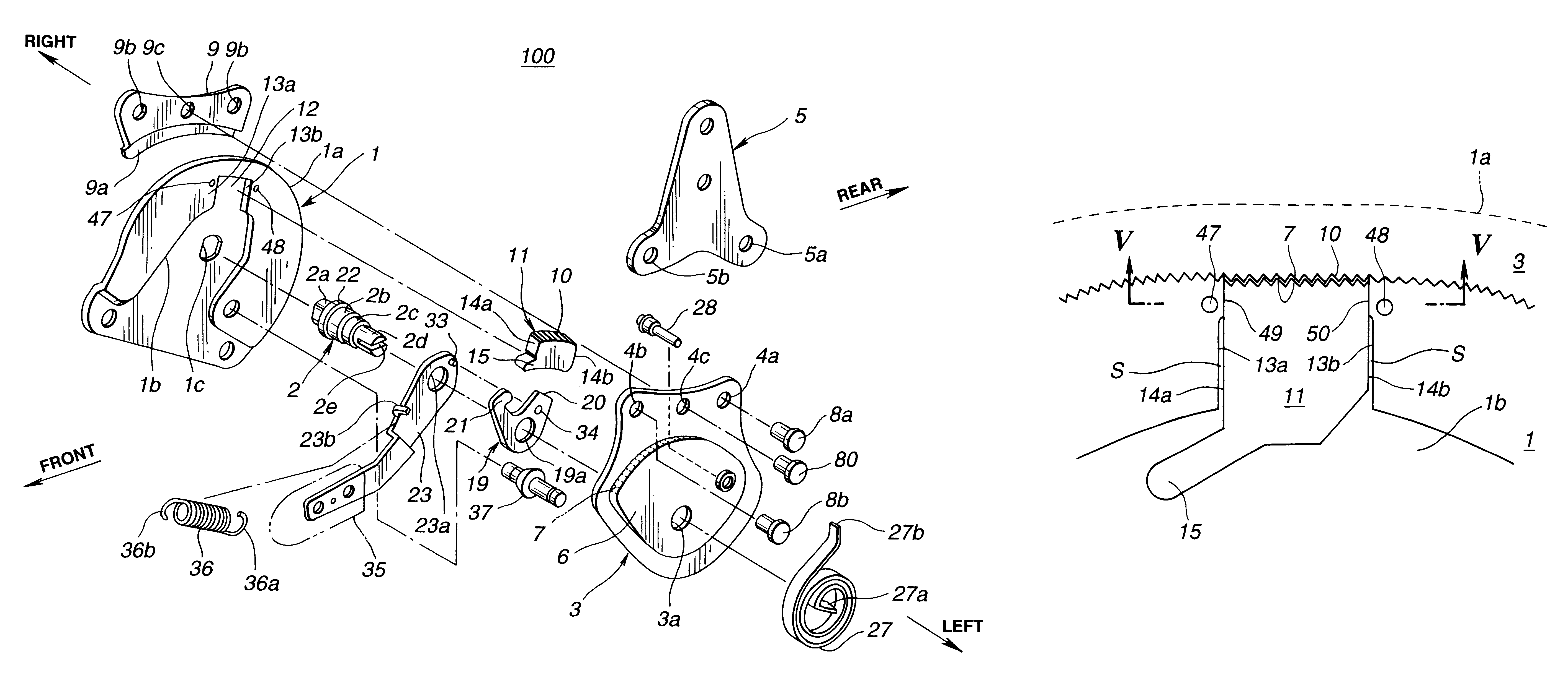
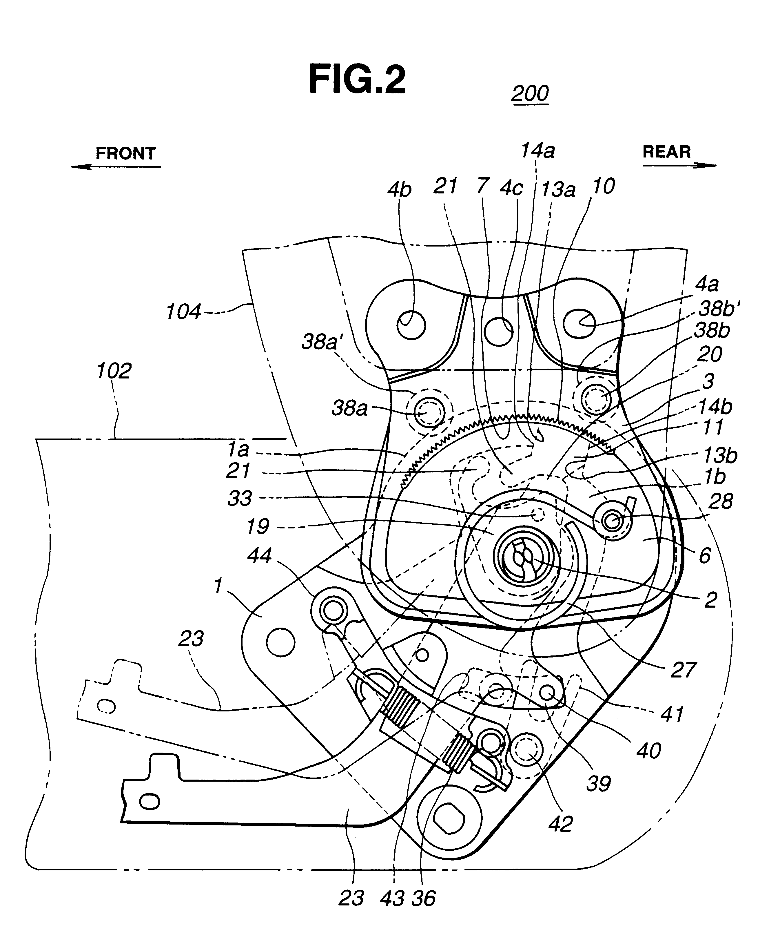
Referring to FIG. 1, there is shown in an exploded manner a seat reclining device 100 which is the present invention.
In the drawing, denoted by numeral 1 is a base plate which is secured to a rear left side of a seat cushion (102, see FIG. 2). A tooth plate 3 is pivotally connected to the base plate 1 through a center shaft 2.
To the tooth plate 3, there is secured an arm member 5 through pins 8a and 8b. For this connection, the arm member 5 and the tooth plate 3 are formed with two pairs of aligned openings (5a, 4a) and (5b, 4b) through which the pins 8a and 8b pass respectively. As will be described in detail hereinafter, each pin 8a or 8b is caulked.
The arm member 5 is secured to a lower left side of a seatback (104, see FIG. 2). Thus, the base plate 1, the center shaft 2, the tooth plate 3 and the arm 5 constitute a left-side pivot mechanism by which the seatback 104 is pivotal relative to the seat cushion 102. Although not shown in the drawing, a right-side pivot mechanism simil...
second embodiment
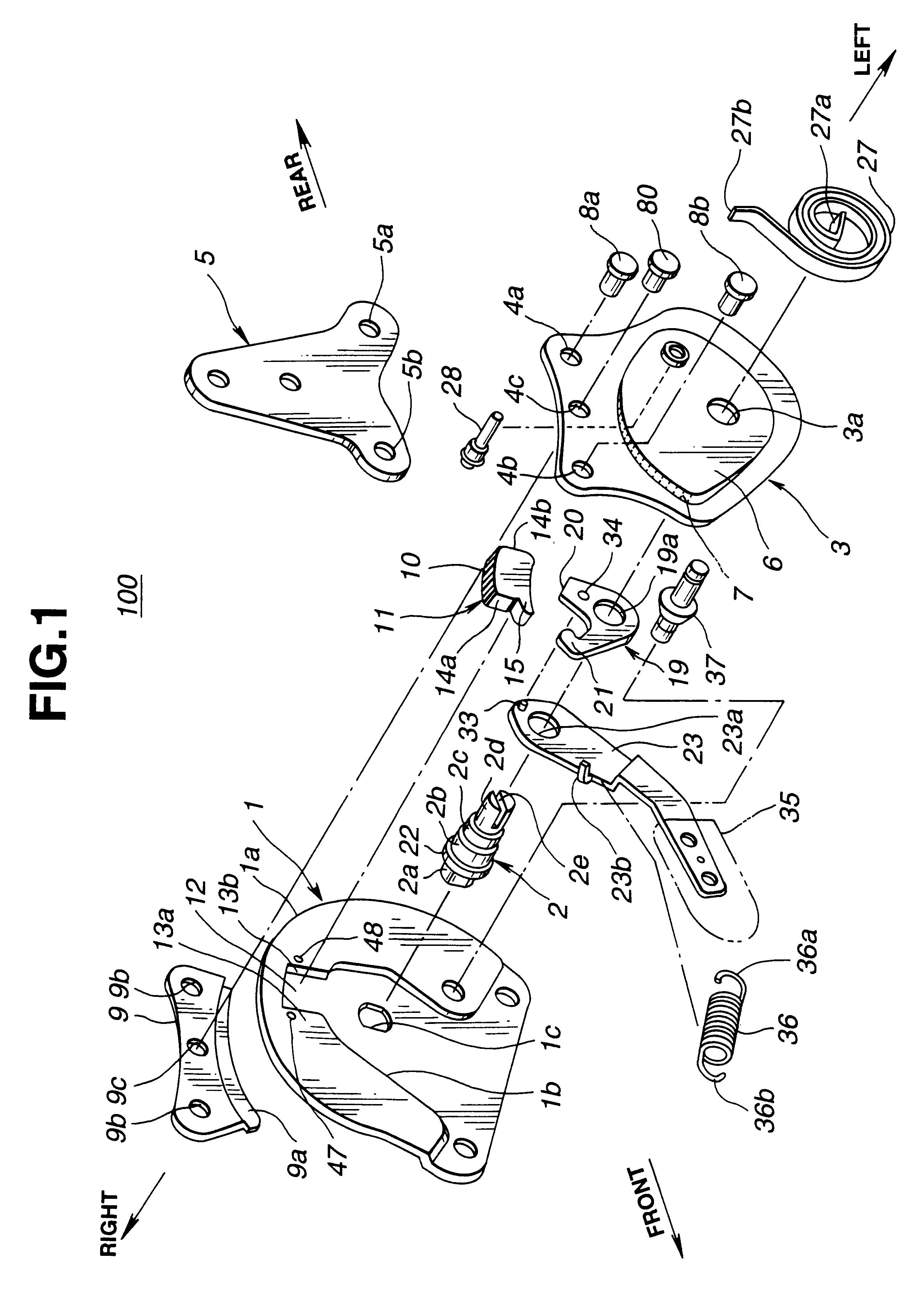
Referring to FIGS. 2 and 3, there is shown a seat reclining device 200 which is the present invention.
Since the second embodiment 200 is similar to the above-mentioned first embodiment 100, detailed explanation will be directed to only portions and parts which are different from those of the first embodiment 100.
In the second embodiment 200, flanged pins 38a and 38b are used in place of the pins 8a, 8b, 80 and the sliding shoe 9 which are employed in the first embodiment 100. That is, the pins 38a and 38b extending from the tooth plate 3 have each a circular flange 38a' or 38b' which is slidably mated with the round upper edge 1a of the base plate 1. With such flanged pins 38a and 38b, undesired separation of the tooth plate 3 from the base plate 1 is prevented and thus stable pivoting of the tooth plate 3 relative to the base plate 1 is assured. Denoted by numeral 44 in FIG. 2 is a lug formed on the base plate 1 to hold one end of the spring 36.
Furthermore, in the second embodiment...
PUM
Abstract
A seat reclining device is provided, which has a base plate secured to a seat cushion; a tooth plate secured to a seatback; a center shaft for permitting the tooth plate to pivot relative to the base plate; first teeth possessed by the tooth plate; a tooth piece having second teeth which are engageable with the first teeth to establish a locked condition between the base plate and the tooth plate, the tooth piece having parallel side walls; and a guide groove defined by the base plate for slidably receiving therein the tooth piece, the guide groove having parallel guide walls which face and contact the parallel side walls of the tooth piece respectively. The parallel side walls are provided near the first teeth with respective projections which are directed toward each other. Due to provision of the projections, the locked engagement between the tooth piece and the tooth plate through the first and second teeth is assuredly kept without producing play even when a marked shock is applied therebetween.
Description
1. Field of the InventionThe present invention relates to seat reclining devices and more particularly to automotive seat reclining devices of a type which employs toothed elements for locking a seatback at a desired angular position relative to a seat cushion.2. Description of the Prior ArtHitherto, various types of seat reclining devices have been proposed and put into practical use particularly in the field of motor vehicles. Some are of a type which employs toothed elements for obtaining a reliable locked condition of the seatback at a desired angular position relative to a seat cushion. That is, in such type seat reclining devices, two toothed elements are employed, which are brought into a meshed engagement when it is needed to lock the seatback at the desired angular position. When it becomes to need to change the angular position of the seatback, the locked engagement between the two toothed elements is cancelled to permit a free pivotal movement of the seatback to a new des...
Claims
Application Information
Patent Timeline
Application Date:The date an application was filed.
Publication Date:The date a patent or application was officially published.
First Publication Date:The earliest publication date of a patent with the same application number.
Issue Date:Publication date of the patent grant document.
PCT Entry Date:The Entry date of PCT National Phase.
Estimated Expiry Date:The statutory expiry date of a patent right according to the Patent Law, and it is the longest term of protection that the patent right can achieve without the termination of the patent right due to other reasons(Term extension factor has been taken into account ).
Invalid Date:Actual expiry date is based on effective date or publication date of legal transaction data of invalid patent.

