Wire-and-thread rimmed frame for eyeglasses

a technology of rim wire and eyeglasses, which is applied in the direction of spectacles/goggles, instruments, spectacles/goggles, etc., can solve the problems of reducing the strength of the rim wire at these restricted places, hardly strong enough to provide an eyeglass frame for practical use, and breaking the eyeglass frame at these restricted places

Inactive Publication Date: 2001-07-24
HYOI ISAO
View PDF3 Cites 40 Cited by
  • Summary
  • Abstract
  • Description
  • Claims
  • Application Information

AI Technical Summary

Problems solved by technology

Such wire which is thin enough to fit in the circumferential groove of the lens "c", however, can be hardly strong enough to provide an eyeglass frame for practical use.
Consequently the inner stress is likely to converge to the boundary "g" between the half-rim "a" and the proximal or distal reinforcement piece "f", resulting in the breaking of the eyeglass frame at these restricted places.
As a matter of fact the rim wire was locally heated and softened when the proximal or distal reinforcement piece was soldered to the rim wire, thus reducing the strength of the rim wire at these restricted places.
As a result the length of high-tension thread "b" is liable to be broken there.
The temple is liable to be loosely fixed when the screws are loosened in the hinge.

Method used


Image

  • Wire-and-thread rimmed frame for eyeglasses
  • Wire-and-thread rimmed frame for eyeglasses
  • Wire-and-thread rimmed frame for eyeglasses

Examples


first embodiment

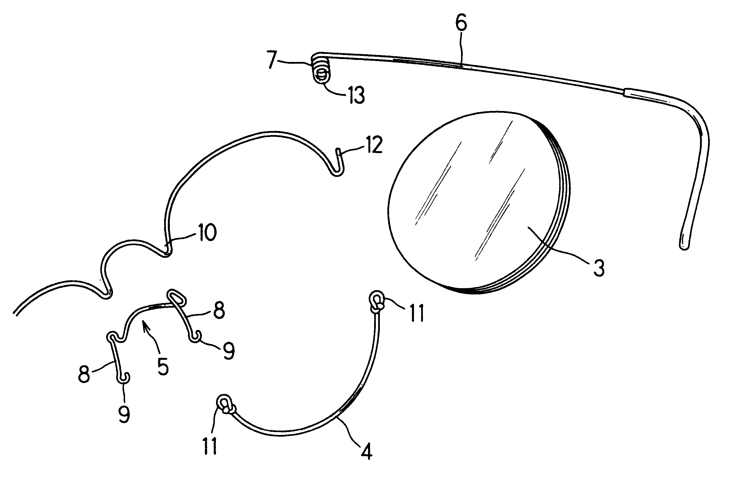
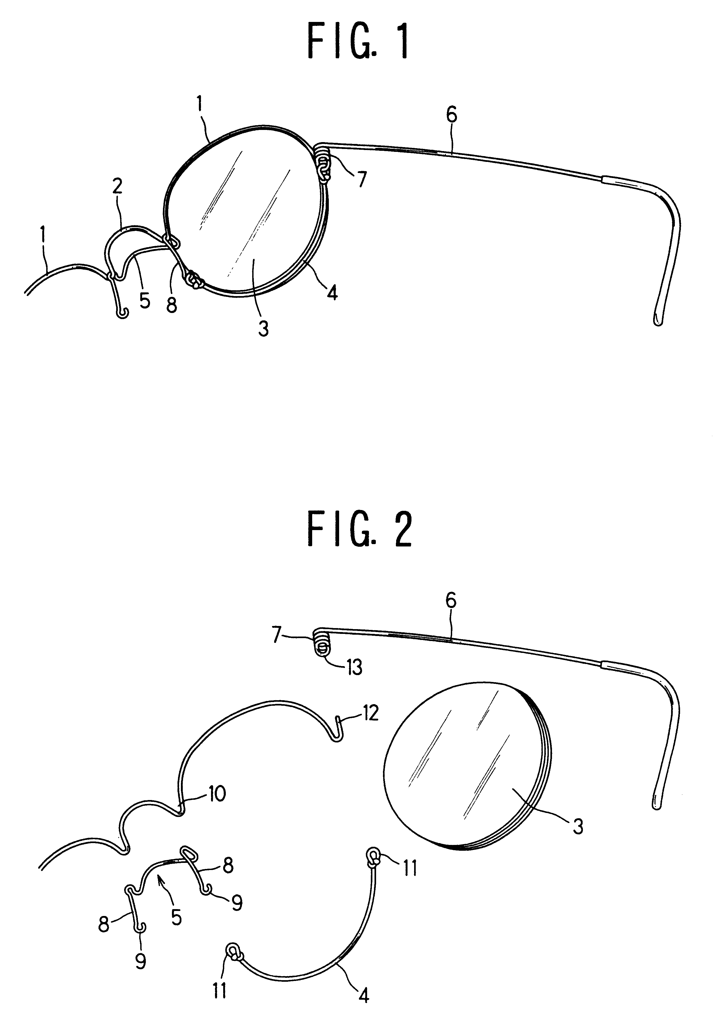
Referring to FIG. 1, a wire-and-thread rimmed frame according to the present invention comprises a single wire so bent as to configure two opposite upper half-rims 1 integrally connected by an intervening bridge 2, two lengths of high-tension thread 4, and an arch-like bridge reinforcement 5. Each length of high-tension thread 4 is stretched round the lower circumference of one or the other lens 3 to hold the lens 3 in cooperation with the upper half-rim 1. Specifically the length of high-tension thread 4 is fitted in the circumferential groove of the lens 3, and is fixed both to one or the other support 8 of the arch-like bridge reinforcement 5 and to the coiled spring 7 of one or the other temple 6. As shown in the drawing, the single wire has a reentrant section formed at each of the bridge-to-rim transitions, and the arch-like bridge reinforcement 5 is fixed to the bridge 2 by hanging its opposite corners from the reentrants of the wire.

Referring to FIG. 2, all parts can be asse...

second embodiment

FIG. 4 shows a wire-and-thread rimmed frame according to the present invention, and FIG. 5 shows the wire-and-thread frame in exploded condition. The frame of FIGS. 4 and 5 is different from that of FIGS. 1 and 2 only in the manner in which each temple 6 is attached to the front. As shown, each half-rim 1 has a lateral extension to form a joint piece 17. The joint piece 17 thus formed has a dependent pivot axle 18. An L-shaped engagement piece 19 is used to fix the temple 6.

As shown, the L-shaped engagement piece 19 has a hook formed on one end, and a ring 21 formed at the other end. The temple 6 has a ring 22 formed at its end. The pivot axle 18 of the lateral extension 17 is inserted in the ring 22 of the temple 6. The L-shaped engagement piece 19 is engaged with the half-rim 1 by hanging from the rim-to-joint reentrant transition 23 and by inserting the pivot axle 18 in the ring 21 of the L-shaped engagement piece 19. Then, the loop 11 of the stretched length of high-tension thre...


PUM


Abstract

Disclosed is an improved wire-and-thread rimmed frame structure for eyeglasses. It has a single wire so bent as to configure two opposite upper half-rims integrally connected by an intervening bridge and two lengths of high-tension thread each stretched round the lower circumference of one or the other lens to hold the lens in cooperation with the upper half rim. The single wire has a reentrant formed at each of the bridge-to-rim transitions, and it further comprises an arch-like bridge reinforcement, which is fixed to the bridge by hanging its opposite corners on the bridge-to-rim reentrants. Each length of high-tension thread is fixed at one end to one or the other support of the arch-like bridge reinforcement and at the other end to one or the other half frame, thereby allowing the length of high-tension thread to apply a stretch to one or the other support of the arch-like bridge as a counter action to the length of high-tension thread being stretched around the lower half circumference of the lens.

Description

1. Field of the InventionThe present invention relates to a wire-and-thread rimmed frame for eyeglasses, which frame uses lengths of high-tension thread fixed to its upper wire half-rims to hold two lens in a pair of glasses.2. Related ArtsA wire-and-thread rimmed frame has two lengths of high-tension thread fixed to its upper wire half-frames for holding the opposite lenses. Use of upper wire half-rims permits reduction of the eyeglass frame in weight and expansion of visual field. FIG. 9 shows a conventional wire-and-thread rimed frame structure. As shown, each semi-circular wire rim "a" has a length of high-tension thread "b" fixed to its opposite ends, thus enabling the lens "c" to be fixedly held within the wire-and-thread loop. The opposite upper half-rims "a" are jointed by the bridge "d", and each half-rim "a" has a joint piece "e" fixed to its outer edge. Each temple is hinged to one or the other half-rim "a" via the joint piece "e" so that the temple may be folded or unfol...

Claims


Application Information

Patent Timeline
Patent Type & Authority Patents(United States)
IPC IPC(8): G02C1/00G02C1/04G02C5/02G02C5/06G02C9/04
CPCG02C1/04G02C5/008G02C2200/10
Inventor HYOI, ISAO
Owner HYOI ISAO
Why Eureka
Try Eureka