Device and method to hold sound insulation in vehicle hood

Inactive Publication Date: 2002-04-30
INT TRUCK INTPROP LLC
View PDF13 Cites 13 Cited by
  • Summary
  • Abstract
  • Description
  • Claims
  • Application Information

AI Technical Summary

Benefits of technology

In view of the above mentioned constraints it is an object of the present invention to provide a surface conforming spring and a mounting structure therefore that is stiff enough to firmly hold an object against a spring conformance surface. It is a further object that the surface conforming spring of the pre

Problems solved by technology

The stiffness that the surface conforming springs could have was also limited by a number of factors.
As is the case with many such systems, in which a surface conforming spring is employed to hold an object against a spring conformance surface, the surface conforming spring is of a constant and limited stiffness.
Because of its limited stiffness the sur

Method used


Image

  • Device and method to hold sound insulation in vehicle hood
  • Device and method to hold sound insulation in vehicle hood
  • Device and method to hold sound insulation in vehicle hood

Examples


Example

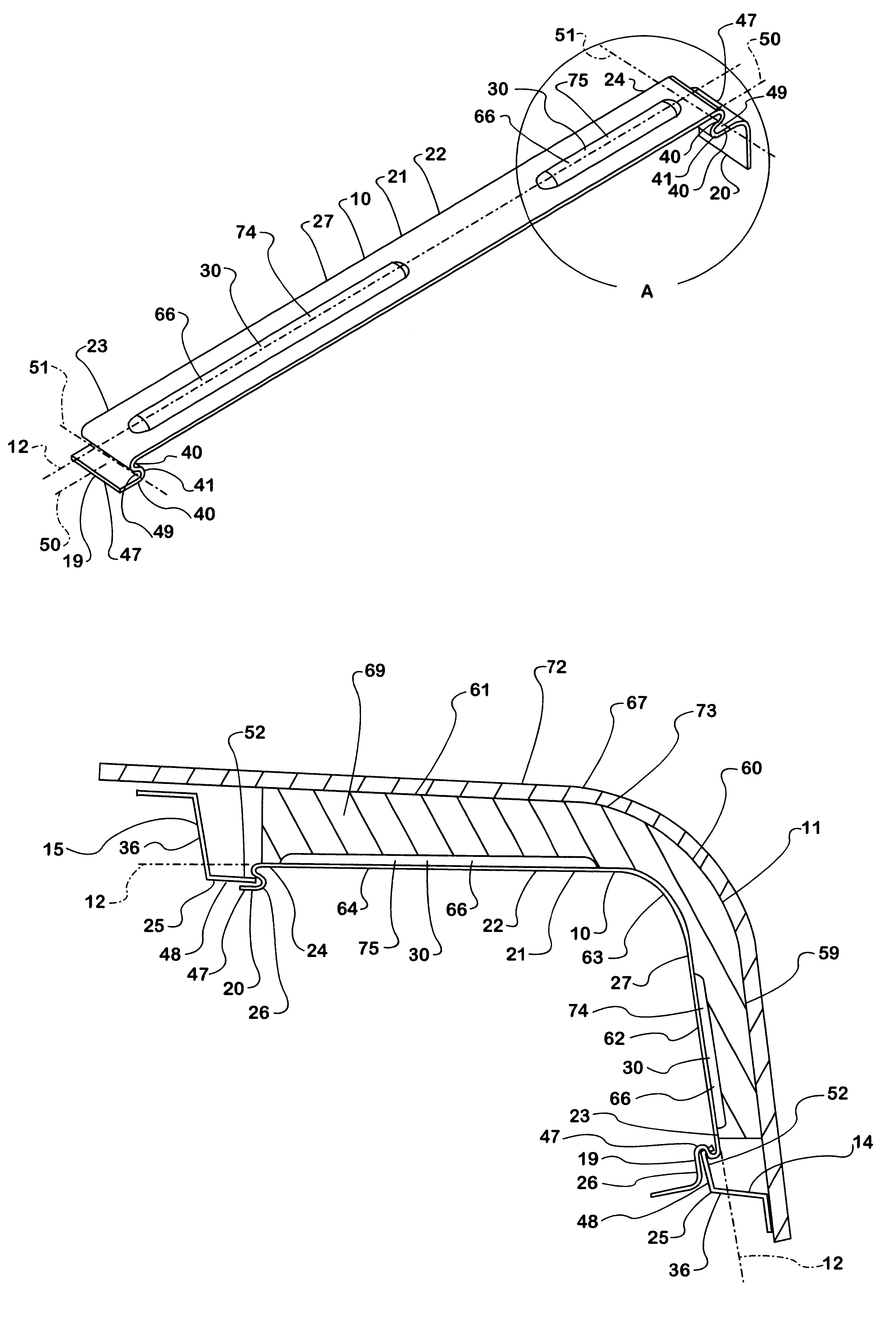
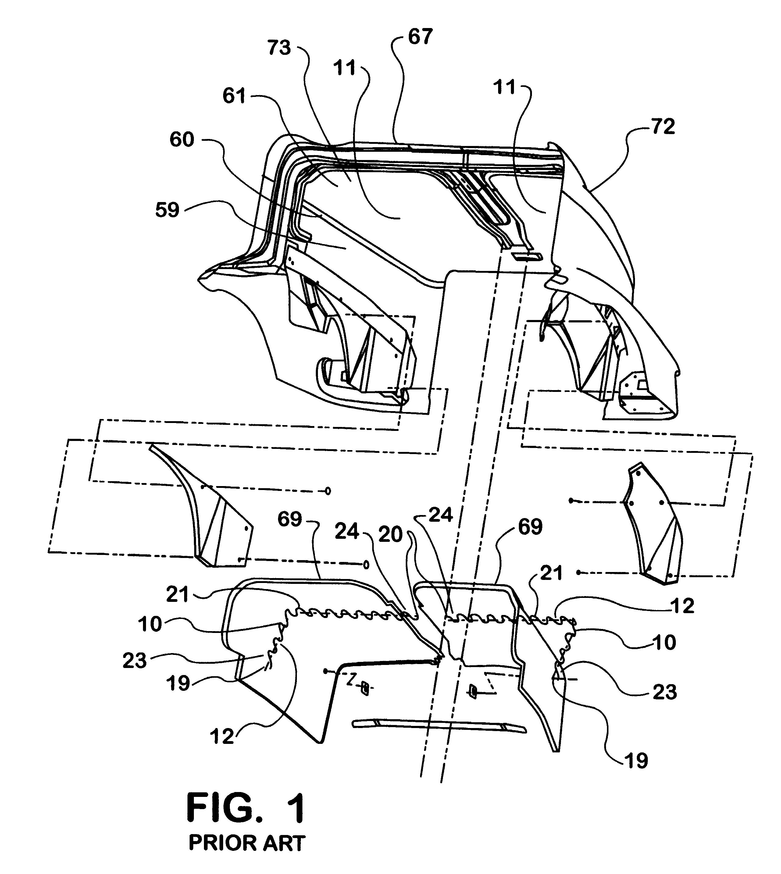
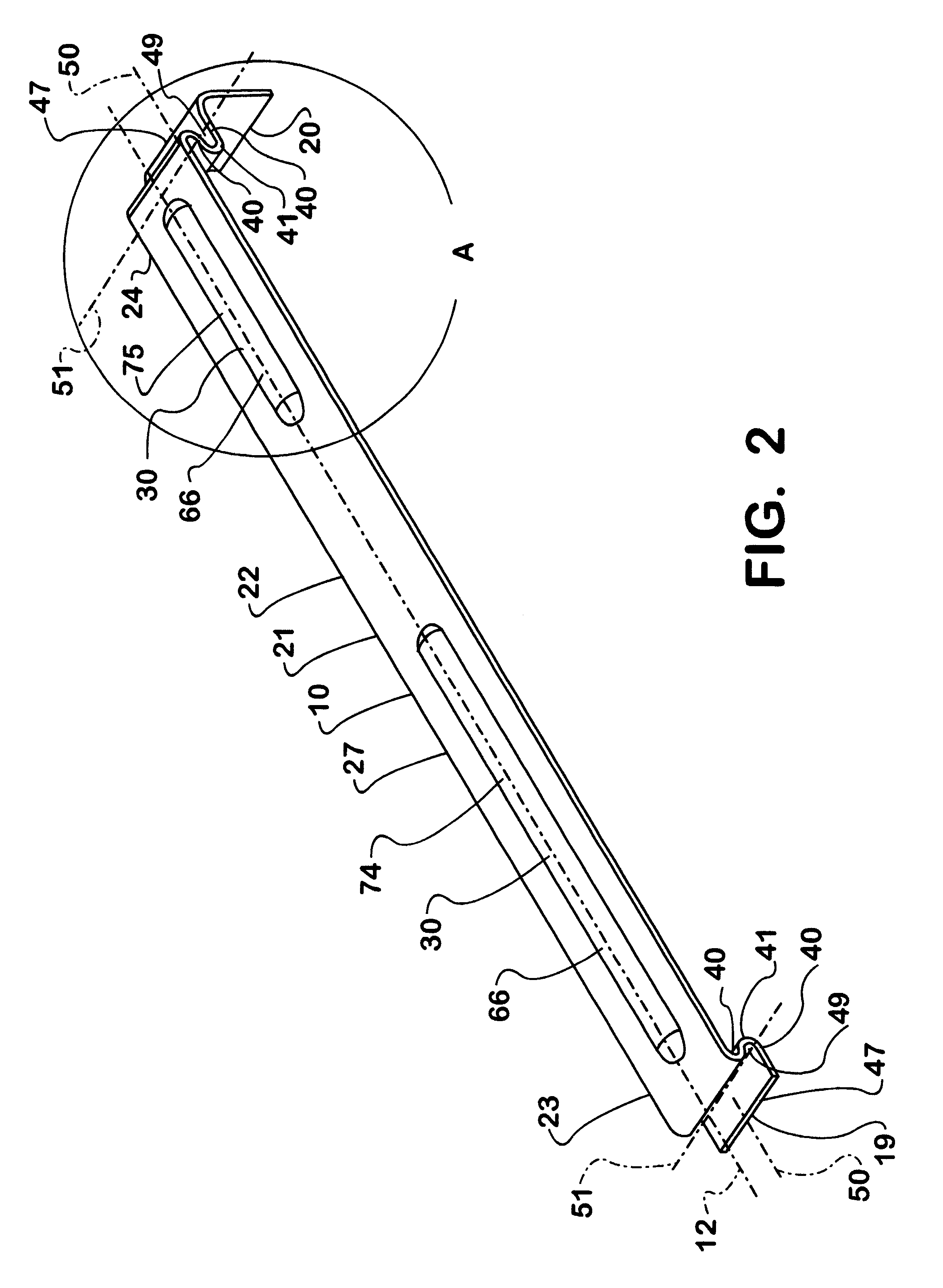
The present invention is a surface conforming spring 10. The surface conforming spring 10 is designed to be mounted adjacent a spring conformance surface 11 which is defined by a spring conformance component 67. The spring conformance surface 11 is a surface that is either concave or convex. The spring conformance surface 11 may have widely varying radii of curvature over the portion of the spring conformance surface 11 adjacent, which the surface conforming spring 10 is to be disposed. The surface conforming spring 10 has a spring body 21 disposed along a longitudinal axis 12 of the surface conforming spring 10. The surface conforming spring 10 may be constructed such that the longitudinal axis 12 may be a curve of virtually any shape when the surface conforming spring 10 is in its free state. In the preferred embodiment, the surface conforming spring 10 is constructed such that the longitudinal axis 12 of the surface conforming spring 10 is a straight line when the surface conform...


PUM


Abstract

A spring designed to be mounted adjacent and in conformance with a convex or concave surface that has varying radii of curvature. The stiffness against bending of the spring varies along its longitudinal axis. The stiffness against bending of various portions of the spring is proportional to the radii of curvature of portions of the surface adjacent which each portion of the spring is to be disposed. The mounting structure for the spring includes female mounting members that are to be engaged to male mounting members. The female mounting members and male mounting members can be engaged to one another by sliding the two components together. The spring and mounting system are particularly well adapted for holding objects adjacent an inner surface of body panels of a vehicle.

Description

The present invention is a spring that is designed to bend along its longitudinal axis and conform to a spring conformance surface that is substantially either convex or concave along the entire portion that the spring is meant to conform to. The spring conformance surface that the spring is designed to conform to may also have greatly varying radii of curvature along the portion that the spring is intended to conform to. Springs that can be bent along their longitudinal axis to conform to such spring conformance surfaces are known. An example of such a prior art spring is shown in FIG. 1. In FIG. 1 the prior art spring is shown in a bent state as it would be disposed when it were installed and conformed to a spring conformance surface such as the underside of a hood of a vehicle which is shown in FIG. 1. Surface conforming springs of the prior art can be of a number of different constructions. Most surface conforming springs have a longitudinal axis central to a body of the spring ...

Claims


Application Information

Patent Timeline
IPC IPC(8): B62D33/06B60R13/02B60R11/00
CPCB60R11/00B62D33/0604B60R13/0206
Inventor DEWEY, DALLAS D.HENDRICKS, MELVIN A.OBERLY, MARK D.
Owner INT TRUCK INTPROP LLC
Why Eureka
Try Eureka