Tapered slot antenna

Inactive Publication Date: 2014-03-27
SAAB AB
View PDF16 Cites 9 Cited by
  • Summary
  • Abstract
  • Description
  • Claims
  • Application Information

AI Technical Summary

Benefits of technology

[0016]The feeding probe is located on the circuit board, from which it is fed. The feeding probe preferably comprises a dielectric coverage surrounding the conductive core. Said dielectric coverage is adapted to fit into said cavity, and at least partially fills the distance between the conductive core and the inner wall. However it is preferred that dielectric coverage is adapted to fit into the cavity of the tapered slot antenna element, such that it can support the tapered slot antenna element. The dielectric coverage of th

Problems solved by technology

The connector and the attachment interface obviously mean additional cost in both material

Method used


Image

  • Tapered slot antenna
  • Tapered slot antenna
  • Tapered slot antenna

Examples


Example

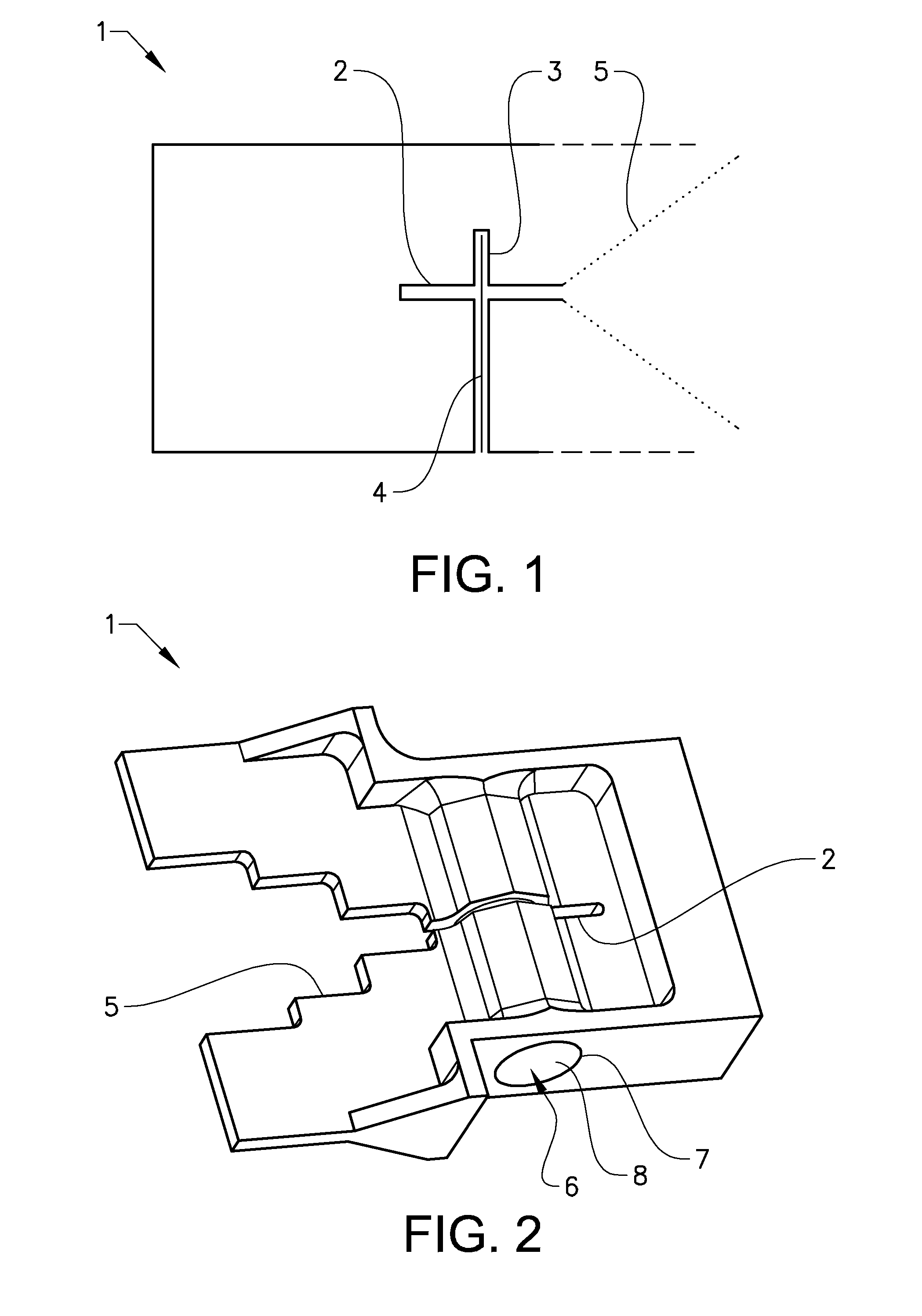
[0027]In FIG. 1 is a principle drawing of the principle of the invention disclosed. In the drawing the tapered slot antenna element 1, the slot line 2 and the layer 3 comprising conductive material surrounding the conductive core 4 are shown. Due to difference in potential between the conductive core 4 and the layer 3 a coaxial field is built up between these two elements 3, 4. A local maximum of the coaxial field is built up where the slot line 4 cuts the layer 3, whereby the coaxial field can feed the slot line 4. The signal fed into the slot line 4 is then transmitted through the slot line 4 and into the tapered notch 5.

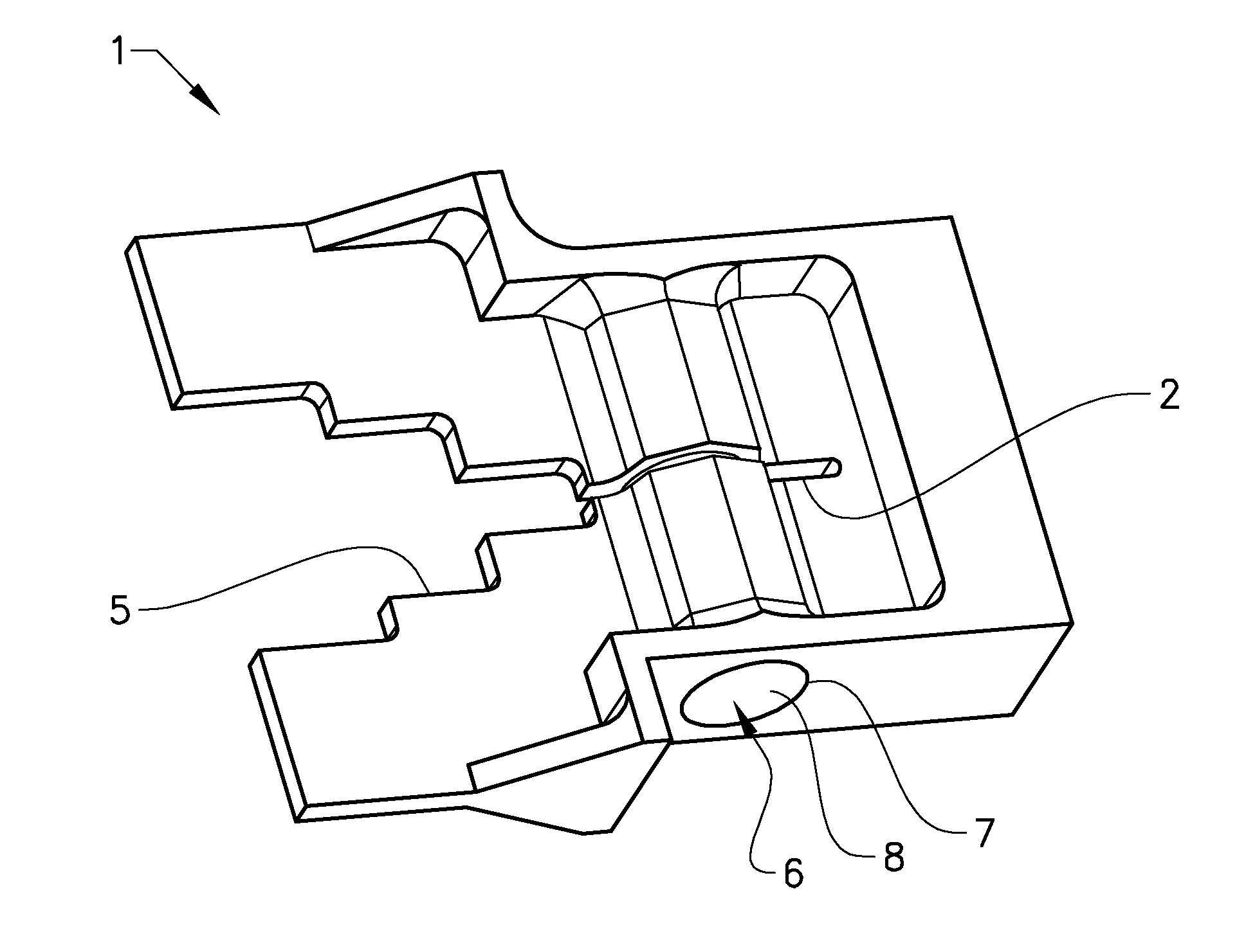
[0028]In FIG. 2 an embodiment of an inventive tapered slot antenna element 1 is shown. The tapered slot antenna element 1 is provided with an aperture with a slot line 2. The aperture 5 is shown as a stepped slot, however other forms of slots is just as possible, e.g. tapered slot, Vivaldi, or bunny ear. The type of aperture 5 is not essential for the invention, w...


PUM


Abstract

The tapered slot antenna element according to the invention comprises a tapered slot with a narrow inner part. The tapered slot antenna element further comprises a cavity for receiving a feeding probe. An inner wall of said is provided with a layer comprising an electric conductive material, and said cavity is provided with an open end. The cavity is adapted such that a feeding probe can be inserted into the cavity through the open end. The layer comprising the electric conductive material is adapted such that the coaxial field can be build up between the feeding probe and said layer of electric conductive material. Hence, said layer can be a homogenous layer or a wire netting or the like, as long as a coaxial field can be build up between the electric conductive layer and the feeding probe.

Description

TECHNICAL FIELD[0001]The present invention relates to the field of antenna technology and especially a tapered slot antenna element, a feeding probe for a tapered slot antenna element and a tapered slot antenna arrangement.BACKGROUND ART[0002]Tapered slot antennas are commonly known within the art. A tapered slot antenna is structured, such that a slot line radiates an electromagnetic wave directed parallel to the plane of the antenna. The slot line is commonly fed by a feeding line, which crosses the slot line. The feeding line is integrated in the tapered slot antenna and is connected to a circuit board. There are antennas in which the circuit board is integrated with the antenna element, these antennas have the antenna and the circuit board in the same plane, and thereby, connector means between the feeding line and the circuit board is not needed, since the feeding line can be etched directly on the circuit board.[0003]However, in some applications it is whished that the antenna...

Claims


Application Information

Patent Timeline
IPC IPC(8): H01Q13/10
CPCH01Q13/10H01Q13/085H01Q21/08
Inventor GEBRETNSAE, MUSSIEJENSEN, YVONNESTENQUIST, ELISABETH
Owner SAAB AB
Why Eureka
Try Eureka