

External force detecting device
- Summary
- Abstract
- Description
- Claims
- Application Information
AI Technical Summary
Benefits of technology
Problems solved by technology
Method used
Image

Examples
first embodiment
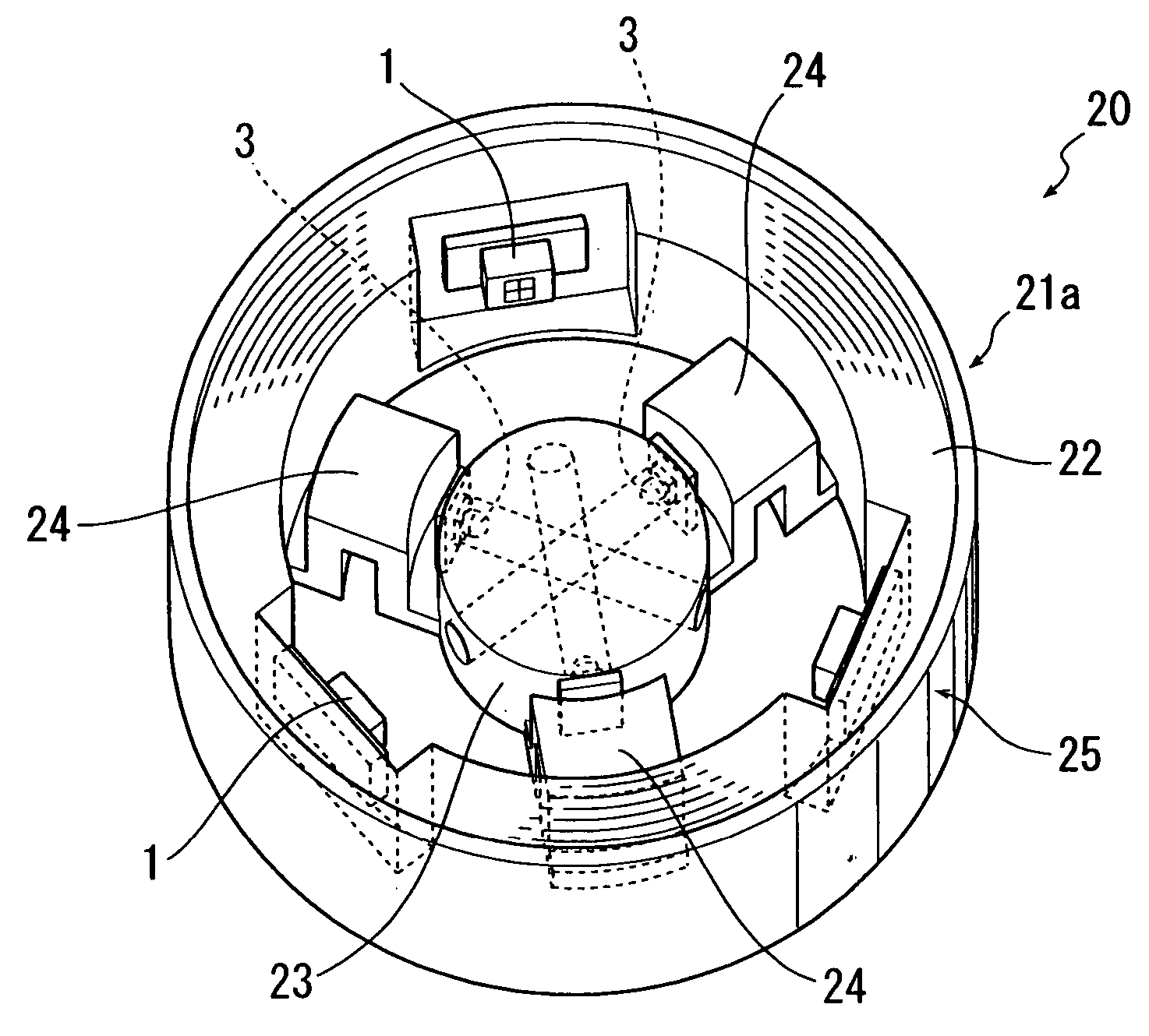
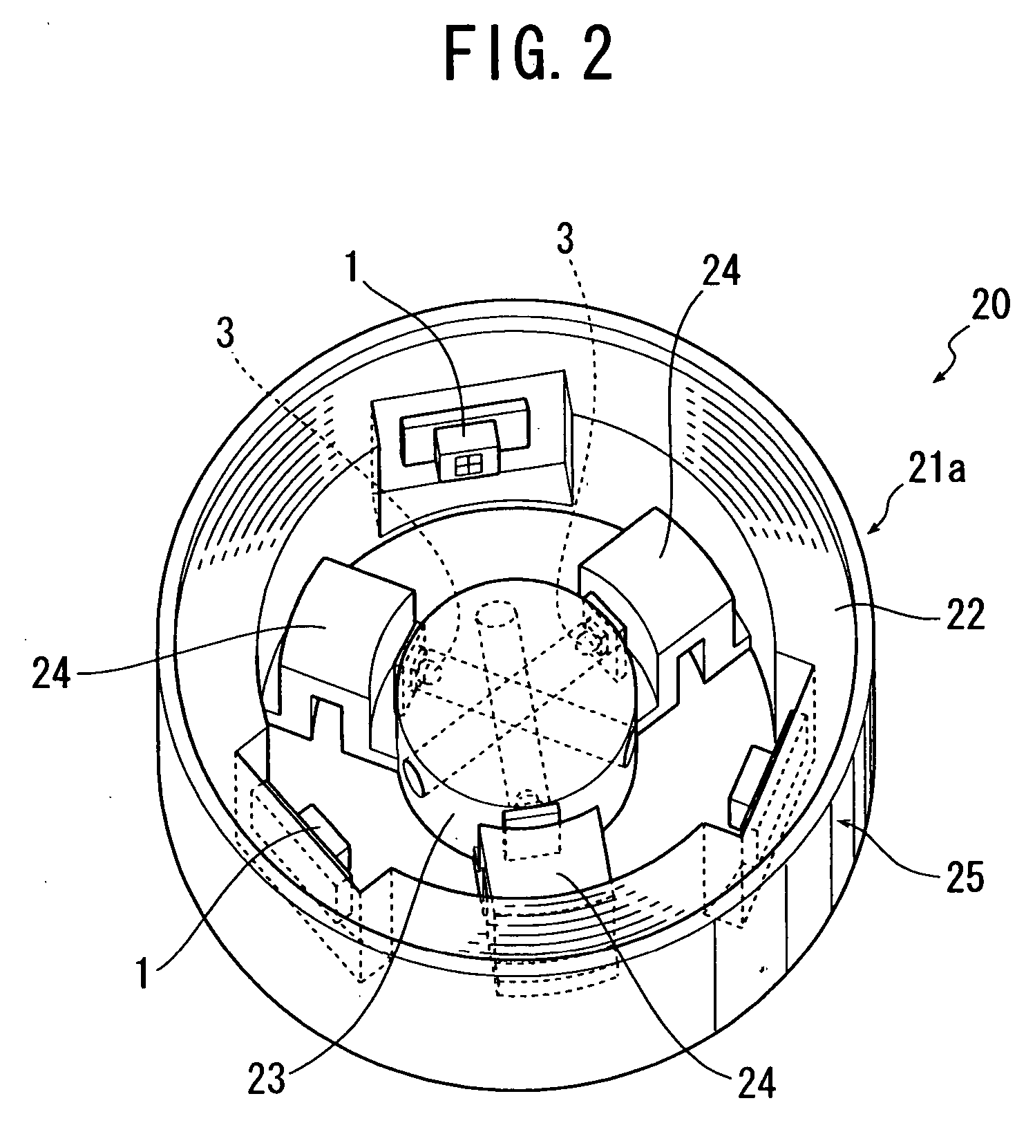
[0039] described above, the optical path length between the light source 3 and the optical sensor 1 is increased by the length of the throughhole formed in the action section 23 compared with the traditional six axis force sensor.
second embodiment
[0040] the present invention will be described with reference to FIGS. 5, 6 and 7. Referring to FIGS. 5 to 7, a six axis force sensor 120 according to the second embodiment has a substantially same frame structure as the six axis force sensor 20 according to the first embodiment, specifically the six axis force sensor 20 is structured with a frame 125 which is made of aluminum alloy formed by cutting work and electric spark machining and which integrally includes a support section 122 shaped into a circular cylinder, an action section 123 disposed centrally inside the support section 122 and having three throughholes passing the center thereof, and three elastic spoke members 124 structured in a crooked shape so as to be elastically deformable with respect to all the directions and adapted to bridge the support section 122 and the action section 123.
[0041] In the present embodiment, the cylinder wall portion constitutes the support section 122, and the center portion constitutes the...
third embodiment
[0047] the present invention will be described with reference to FIGS. 8, 9 and 10. Referring to FIGS. 8 to 10, a six axis force sensor 220 according to the third embodiment has a frame structure basically same as that of the six axis force sensor 20 according to the first embodiment, specifically is structured with a frame 225 which is made of aluminum alloy formed by cutting work and electric spark machining and which integrally includes a support section 222 shaped into a circular cylinder, an action section 223 disposed centrally inside the support section 222 and having three throughholes passing the center thereof, and three elastic spoke members 224 structured in a crooked shape so as to be elastically deformable with respect to all the directions and adapted to bridge the support section 222 and the action section 223.
[0048] In the present embodiment, the cylinder wall portion constitutes the support section 222, and the center portion constitutes the action section 223, but...
PUM
 Abstract
Description
Claims
Application Information