
Sealing device

Active Publication Date: 2005-09-15
CHANGZHOU SANYOU DIOR INSULATION MATERIALS MFG
View PDF10 Cites 12 Cited by
  • Summary
  • Abstract
  • Description
  • Claims
  • Application Information

AI Technical Summary

Benefits of technology

[0012] Another object of the present invention is to provide a sealing device, wherein each of the fasteners is mounted on the door of the thermal device, the fastener provides a clipping force to substantially mount the heat sealing layer on the supporting frame. In other words, the fastener functions not only as a regular fastener to mount the heat sealing layer on the door of the thermal but also as a snap fastener to retain the supporting frame in position.
[0013] Another object of the present invention is to provide a sealing device, wherein each of the fasteners has a spiral retention base constructed by a bent wire such that the fastener can be easily mounted to the supporting frame by simply turning the retention base into the supporting frame.
[0014] Another object of the present invention is to provide a sealing device, which does not require altering the original simple structure of the sealing device so as to reduce the manufacturing cost of the heat sealing layer incorporating with the fasteners.
[0015] Another object of the present invention is to provide a sealing device, wherein no expensive or complicated structure is required to employ in the present invention in order to achieve the above mentioned objects. Therefore, the present invention successfully provides an economic and efficient solution not only for providing a simple configuration for sealing the gap of the thermal but also for enhancing the practice use of the present invention.

Problems solved by technology

However, the conventional gasket has several drawbacks.
Once the elasticity of the gasket is reduced, the gasket cannot effectively seal the gap between the container body and the door such that the heat is started to escape from the thermal chamber to outside through the gap.
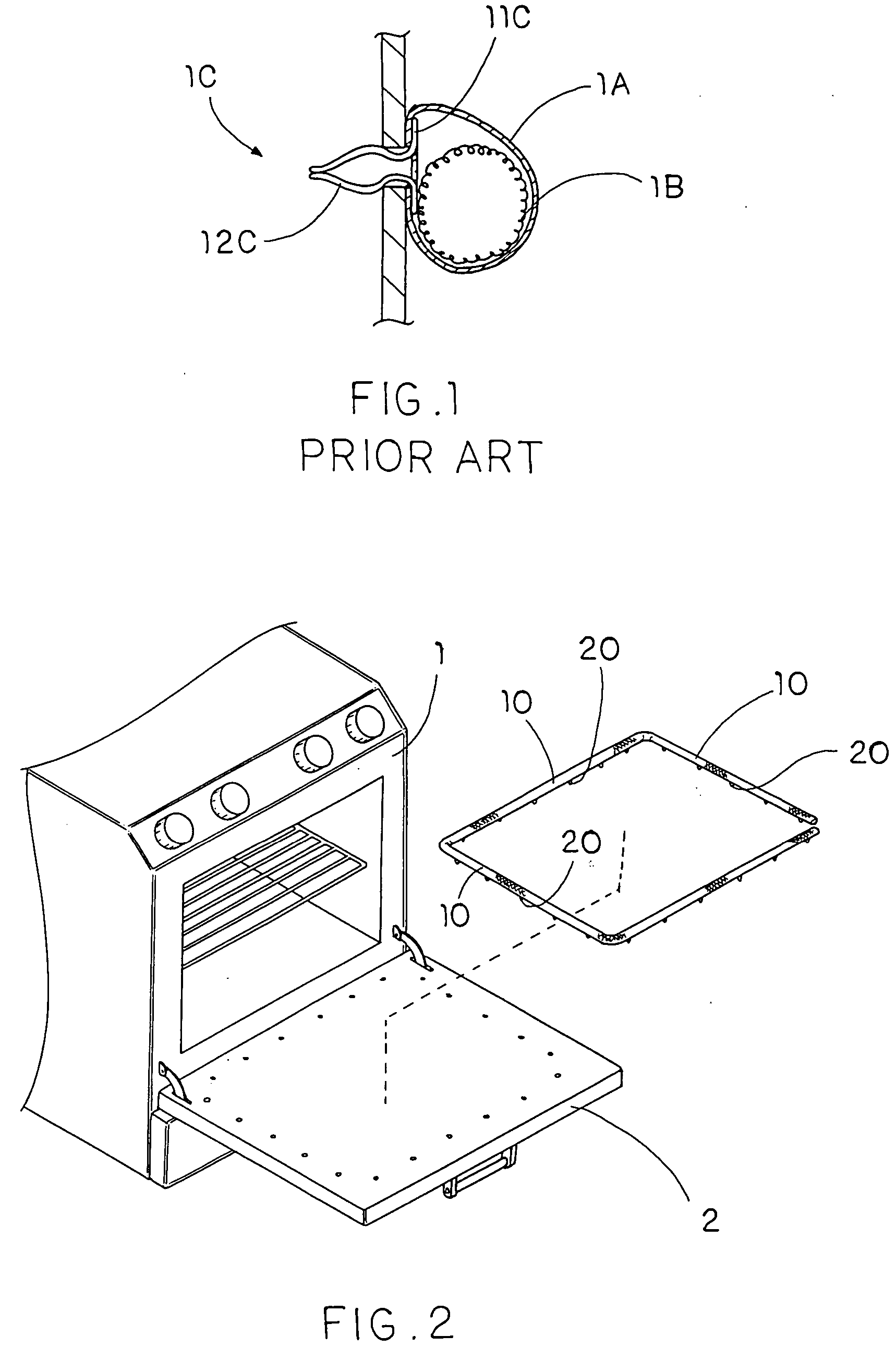
However, since the base portion 11C of each of the fasteners 1C is mounted between the elongated core 1B and the outer jacket 1A, the fasteners 1C cannot substantially support the total weight of the elongated core 1B and the outer jacket 1A after a period of time usage.
Such gasket losses the heat resistance ability when the outer jacket 1A is broken.
In addition, the manufacturing process of such gasket is complicated since each of the fasteners 1C must be precisely mounted along the gasket at a position that the base portion 11C of each of the fasteners 1C is sandwiched between the outer jacket 1A and the elongated core 1B.
Therefore, the complicated structure of such gasket not only increases the manufacturing cost thereof but also is disadvantage in practice use.

Method used


Image

  • Sealing device
  • Sealing device
  • Sealing device

Examples


Embodiment Construction

[0027] Referring to FIGS. 2 and 3 of the drawings, a sealing device according to a preferred embodiment of the present invention is illustrated, wherein the sealing device is adapted for incorporating with a thermal device having a container body 1 and a door 2 operatively connected with the container body 1 so as to seal a gap between a container body 1 and the door 2.

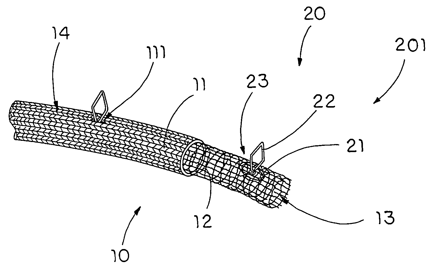
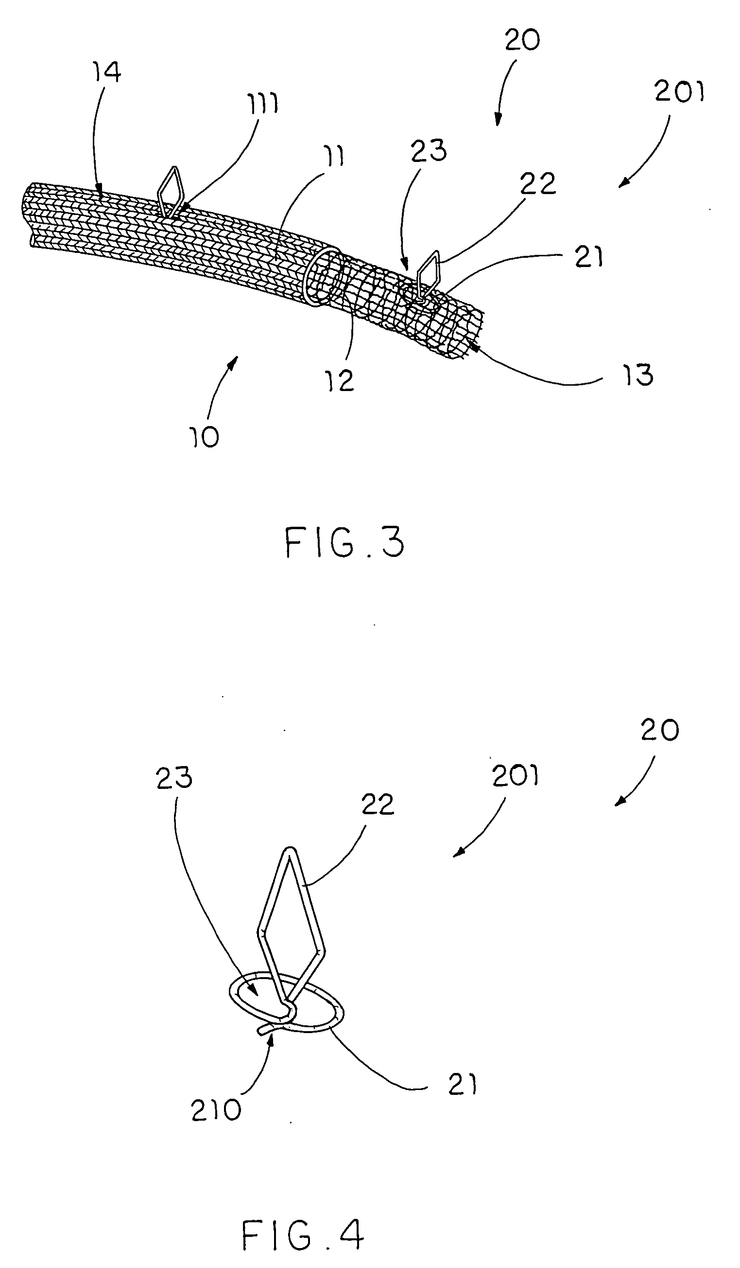
[0028] As shown in FIG. 3, the sealing device comprises an elongated sealing member 10 and a fastening means for fastening the sealing member 10 along the perimeter of the door 2 of the thermal device.

[0029] The sealing member 10 comprises a tubular heat sealing layer 11 and a tubular supporting frame 12, having a flexible ability, coaxially received in the heat sealing layer 11 and defining a deformable channel 13 within the supporting frame 12.

[0030] The fastening means comprises a plurality of fasteners 20 spacedly mounted along the sealing member 10, wherein each of the fasteners 20 has a retention base 21 disp...


PUM


Abstract

A sealing device includes an elongated sealing member and a plurality of fasteners spacedly mounted along the sealing member. The sealing member includes a tubular heat sealing layer and a tubular supporting frame, having a flexible ability, coaxially received in the heat sealing layer and defining a deformable channel within the supporting frame. Each of the fasteners has a retention base disposed within the deformable channel and a engagement head outwardly extended from the retention base through the supporting frame and the heat sealing layer in such a manner that the supporting frame and the heat sealing layer are sandwiched between the retention base of each of the fasteners and the engagement head thereof, so as to retain the supporting frame within the heat sealing layer in position.

Description

BACKGROUND OF THE INVENTION [0001] 1. Field of Invention [0002] The present invention relates to gaskets, and more particularly to a sealing device for a thermal device, which is adapted to fasten with a door of the thermal device to sealedly enclose the thermal chamber therein. [0003] 2. Description of Related Arts [0004] A thermal appliance, such as oven, generally generates heat within a thermal chamber therein, wherein the thermal appliance comprises a container body and a door pivotally mounted to the container body to form the thermal chamber within the container body and the door. In order to prevent the heat from escaping the thermal chamber through the gap between the container door and the door, a gasket is typically used to mount on the door to seal the gap. [0005] A conventional gasket is made of rubber and is securely fastened at the perimeter of the door such that when the door is pivotally folded to close the container body, the gasket is sealedly sandwiched between t...

Claims


Application Information

Patent Timeline
IPC IPC(8): E06B7/16
CPCY10S277/937F24C15/021
Inventor QIANG, MI
Owner CHANGZHOU SANYOU DIOR INSULATION MATERIALS MFG
Learn More