Method and apparatus for control of dual collapsible mandrels

a mandrel and collapsible technology, applied in the field of methods and apparatus for controlling the dual collapsible mandrel, can solve the problems of substantial time and money loss for the tire manufacturer, non-uniformity in the size and/or diameter of the rims of the tires formed on such mandrels,

Inactive Publication Date: 2003-08-05
DAVIAN ENTERPRISES LLC
View PDF4 Cites 22 Cited by
  • Summary
  • Abstract
  • Description
  • Claims
  • Application Information

AI Technical Summary

Benefits of technology

The present invention relates to an apparatus used for expanding and contracting parts made from materials such as rubber or plastic. This device uses pressure fluid (air) to move certain components called segments which are attached to a cylinder. By providing one main source of air, all the segments on both sides of the machine can be expanded or retracted at roughly the same time. This results in more uniform and accurate part production.

Problems solved by technology

The technical problem addressed in this patent relates to improving the accuracy and consistency of tire production through better design and control of the mold used during the shaping process. Specifically, it focuses on developing a smaller, more flexible shaping drum that can accommodate different sized tire carriages while maintaining stable contact with the tire's beads. Previous solutions had limitations including difficulty achieving precise alignment between the mandrels and lack of flexibility in controlling their movement.

Method used


Image

  • Method and apparatus for control of dual collapsible mandrels
  • Method and apparatus for control of dual collapsible mandrels
  • Method and apparatus for control of dual collapsible mandrels

Examples


Embodiment Construction

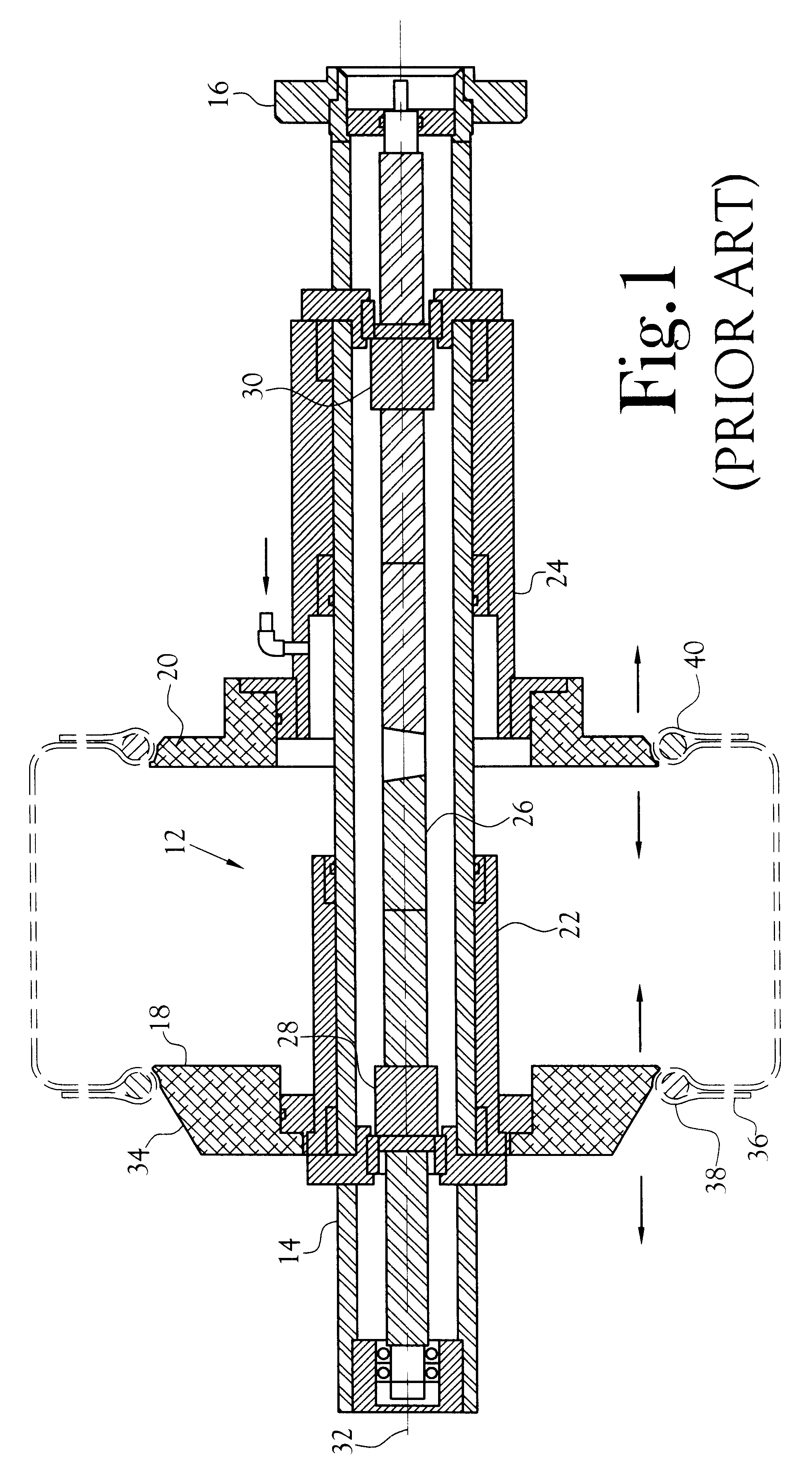
With reference to the prior art tire shaping drum depicted in FIG. 1, the drum 12 includes a central shaft 14 which is affixed at one of its ends 16 to the drive shaft of a conventional drive unit (not shown) whereby the central shaft 14 may be rotated upon rotation of the drive shaft. First and second circular solid mandrels 18,20 are mounted on the central shaft 14 at spaced apart locations along the length of the central shaft. Each mandrel is slidably mounted on the central shaft as by a respective sleeve 22,24 that encircles the central shaft and is slidable along the length of the central shaft. Axial movement of each mandrel along the central shaft may be effected by means of a left-handed and right-handed lead screw 26 whose rotation acts through first and second lead nuts 28,30 that are secured to respective ones of the first and second mandrels, to move the mandrels simultaneously axially toward or away from one another.

The sleeve 22,24 each of the prior art mandrels depic...


PUM

PropertyMeasurementUnit
Angleaaaaaaaaaa
Thicknessaaaaaaaaaa
Forceaaaaaaaaaa

Abstract

A method and apparatus providing for minimization of the separation of a plurality of radially collapsible, generally circular, mandrels which are mounted for axial movement along the longitudinal axis of a central shaft. The method and apparatus is useful for shaping of a green vehicle tire carcass employing a shaping drum which includes dual mandrels which are axially displace able along the longitudinal axis of the drum and adapted to engage respective ones of first and second beads of the carcass.

Description


Claims


Application Information

Patent Timeline
Owner DAVIAN ENTERPRISES LLC
Why Eureka
Try Eureka