Expandable stent and method for delivery of same

Inactive Publication Date: 2005-02-22
EVYSIO MEDICAL DEVICES ULC
View PDF185 Cites 58 Cited by
  • Summary
  • Abstract
  • Description
  • Claims
  • Application Information

AI Technical Summary

Benefits of technology

In yet another embodiment of the invention, the stent may be secured (e.g. by suturing) to an existing endoluminal prosthesis such as Gortex™ material or to biological material such as basilic vein. In this regard, securing of the stent t

Problems solved by technology

The self-expanding stents were found by some investigators to be deficient since, when deployed, they could place undue, permanent stress on the walls of the body passageway.
Further, upon expansion, the stent would shorten in length in an unpredictable fashion thereby reducing the reliability of the stent.
This led to the development of various stents which were controlla

Method used


Image

  • Expandable stent and method for delivery of same
  • Expandable stent and method for delivery of same
  • Expandable stent and method for delivery of same

Examples


Embodiment Construction

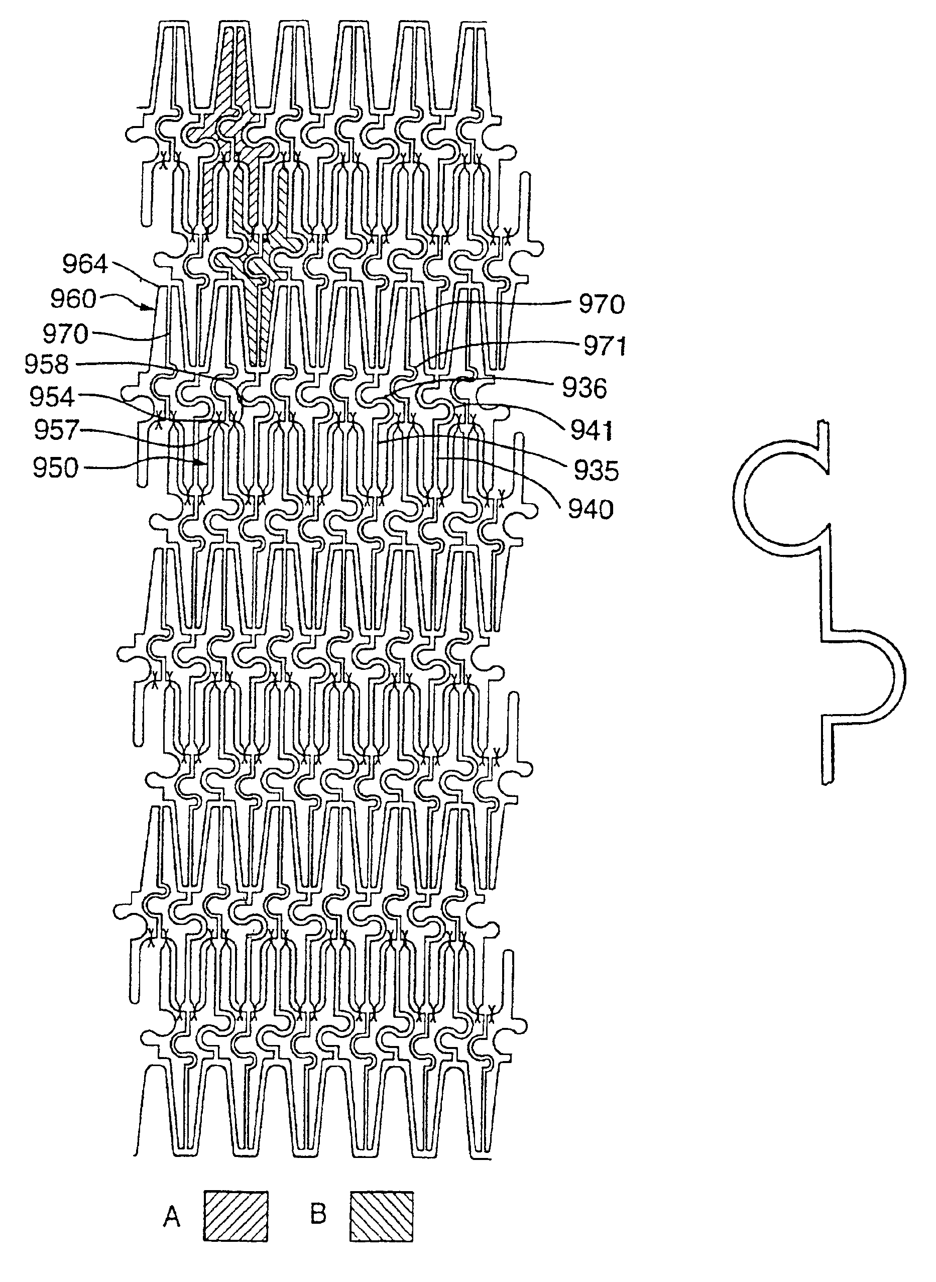
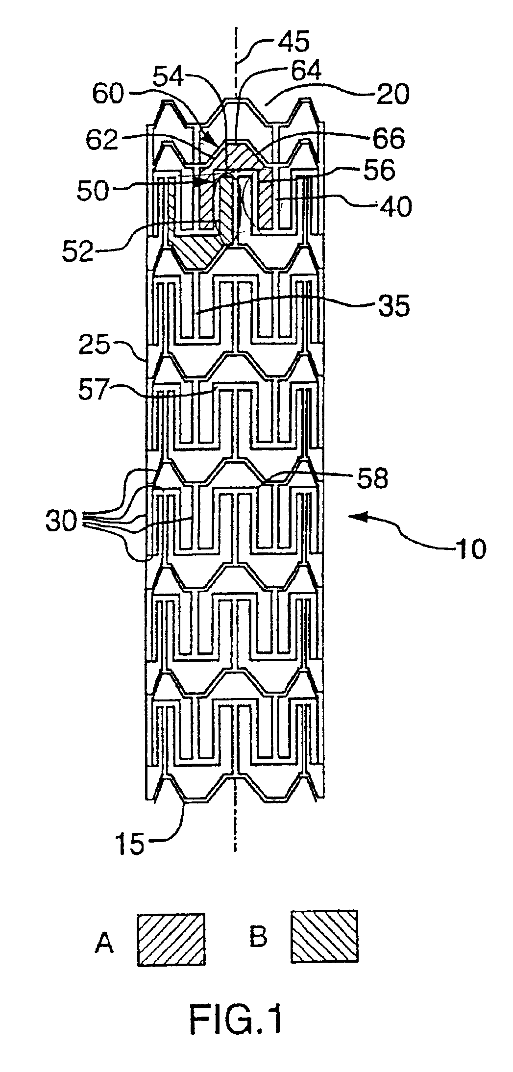
With reference to FIG. 1, there is illustrated a stent 10. Stent 10 comprises a proximal end 15 and a distal end 20. Stent further comprises a tubular wall 25 disposed between proximal end 15 and distal end 20. As illustrated, tubular wall 25 is porous. The porosity of tubular wall 25 is defined by a plurality of intersecting members 30. Intersecting members 30 define a first repeating pattern designated A in FIG. 1.

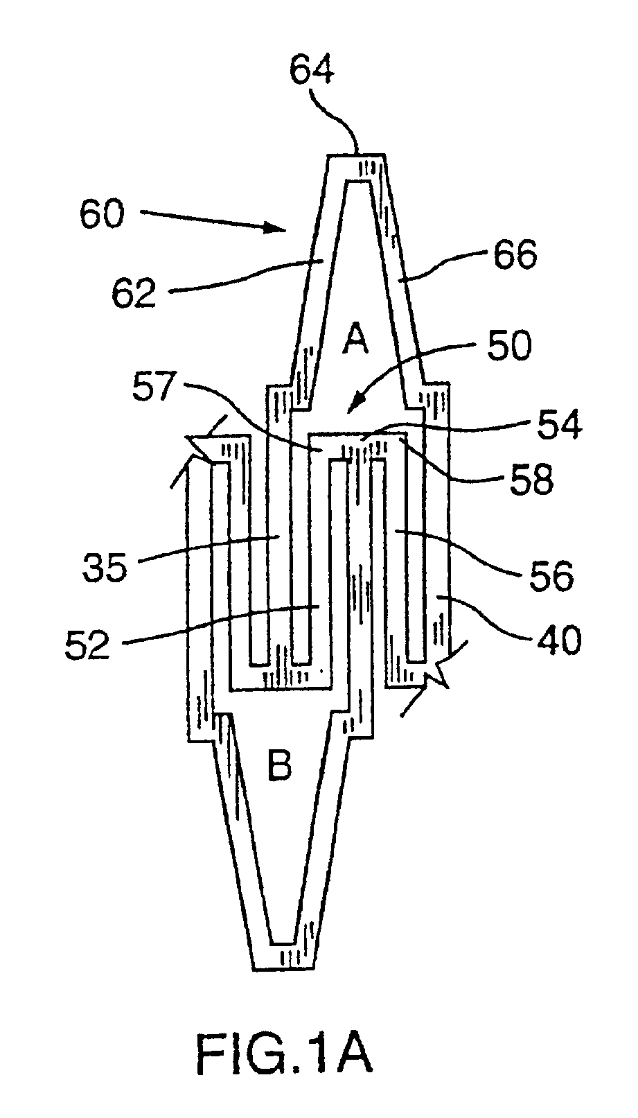
As illustrated and with further reference to FIG. 1A, repeating pattern A is a polygon comprising a pair of side walls 35,40. Side walls 35,40 are substantially parallel to a longitudinal axis 45 of stent 10 and thus side walls 35,40 may be considered to be longitudinal struts (indeed with reference to each of the drawings, side walls may also be considered to be longitudinal struts). Side walls 35,40 are connected by a concave-shaped wall 50 and a convex-shaped wall 60.

As illustrated, concave-shaped wall 50 is made up of a trio of segments 52,54,56. In the illustrated e...


PUM


Abstract

An expandable stent comprising a proximal end and a distal end in communication with one another and a tubular wall disposed between the proximal end and the distal end. The tubular wall has a longitudinal axis and a porous surface defined by a plurality of intersecting members comprising a series of longitudinal struts disposed substantially parallel to the longitudinal axis of the stent. Each longitudinal strut in the series comprises flexure means for substantially complementary extension and compression of a diametrically opposed pair of the longitudinal struts upon flexure of the stent. The stent is expandable from a first, contracted position to a second, expanded position upon the application of a radially outward force on the stent. The provision of such flexure means in the series of longitudinal struts leads to a very desirable balance of lateral flexibility of the unexpanded stent and radial rigidity of the expanded stent.

Description

TECHNICAL FIELDThe present invention relates to an expandable stent.BACKGROUND ARTStents are generally known. Indeed, the term “stent” has been used interchangeably with terms such as “intralurminal vascular graft” and “expansible prosthesis”. As used throughout this specification the term “stent” is intended to have a broad meaning and encompasses any expandable prosthetic device for implantation in a body passageway (e.g. a lumen or artery).In the past six to eight years, the use of stents has attracted an increasing amount of attention due the potential of these devices to be used, in certain cases, as an alternative to surgery. Generally, a stent is used to obtain and maintain the patency of the body passageway while maintaining the integrity of the passageway. As used in this specification, the term “body passageway” is intended to have a broad meaning and encompasses any duct (e.g. natural or iatrogenic) within the human body and can include a member selected from the group co...

Claims


Application Information

Patent Timeline
IPC IPC(8): A61F2/06A61F2/00A61F2/88A61F2/915
CPCA61F2/91A61F2/915A61F2002/825A61F2002/828A61F2002/91525A61F2230/0013A61F2002/91575A61F2210/0019A61F2250/0018A61F2250/0029A61F2250/0036A61F2002/91533
Inventor PENN, IAN M.RICCI, DONALD R.
Owner EVYSIO MEDICAL DEVICES ULC
Why Eureka
Try Eureka