AI technical title is built by Patsnap AI team. It summarizes the technical point description of the patent document.
a stent and expandable technology, applied in the field of expandable stents and methods for delivery, can solve the problems of reducing the reliability of the stent, and applying sufficient force to maintain the patency of the body passageway
Inactive Publication Date: 2005-04-19
EVYSIO MEDICAL DEVICES ULC
View PDF183 Cites 39 Cited by
Summary
Abstract
Description
Claims
Application Information
AI Technical Summary
This helps you quickly interpret patents by identifying the three key elements:
Problems solved by technology
Method used
Benefits of technology
Benefits of technology
[0023]Thus, in this aspect of the present invention, we have now discovered that the use of flexure means in the series of longitudinal struts leads to a very desirable balance of lateral flexibility of the unexpanded stent and radial rigidity of the expanded stent. Practically, the flexure means confers lateral flexibility to the unexpanded stent by allowing diametrically opposed pairs of the longitudinal struts to undergo substantially complementary extension and compression. If one considers a stent in a flexed state, a first longitudinal strut disposed at the tangent of the bend (i.e. in two dimensions) will expand in response to the bending moment. In contrast, a second longitudinal strut disposed diametrically opposite (this can mean above, below or in the same radial plane as) the first longitudinal strut will compress in response to the bending bend moment. Generally, the degree of extension and compression will be substantially complementary. In other words, in most cases, the first longitudinal strut will expand and lengthen a first distance and the second longitudinal strut will compress and shorten a second distance. Preferably, the first distance is greater than the second distance and most preferably, the sum of the first distance and the second distance is substantially equal to the sum of the original lengths of the first longitudinal strut and the second longitudinal strut.
[0055]In yet another embodiment of the invention, the stent may be secured (e.g by suturing) to an existing endoluminal prosthesis such as Gortex™ material or to biological material such as basilic vein. In this regard, securing of the stent to the existing endoluminal prosthesis or biological material may be facilitated by designing the stent such that an end of the stent comprises an annular row of the above-mentioned polygons is having a convex-shaped wall with a flat apex.
Problems solved by technology
The self-expanding stents were found by some investigators to be deficient since, when deployed, they could place undue, permanent stress on the walls of the body passageway.
Further, upon expansion, the stent would shorten in length in an unpredictable fashion thereby reducing the reliability of the stent.
This led to the development of various stents which were controllably expandable at the target body passageway so that only sufficient force to maintain the patency of the body passageway was applied in expanding the stent
Further, implantation of the stent disclosed in the '997 application can be difficult in certain situations where the unexpanded stent must travel through a significantly curved pathway to the target body passageway.
Method used
Image
Click on the blue label to locate the original text in one second.
Reading with bidirectional positioning of images and text.
Examples
Embodiment Construction
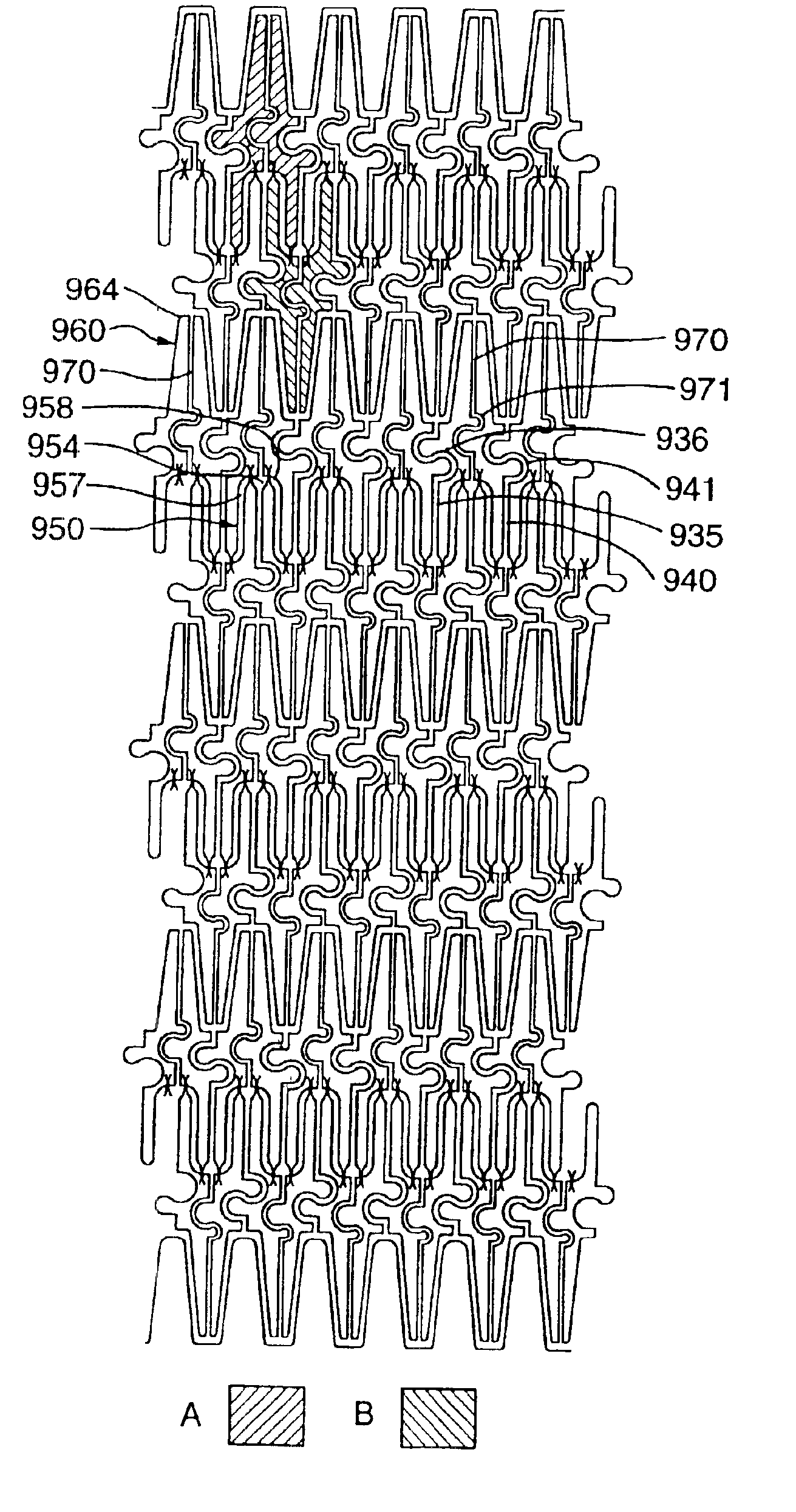
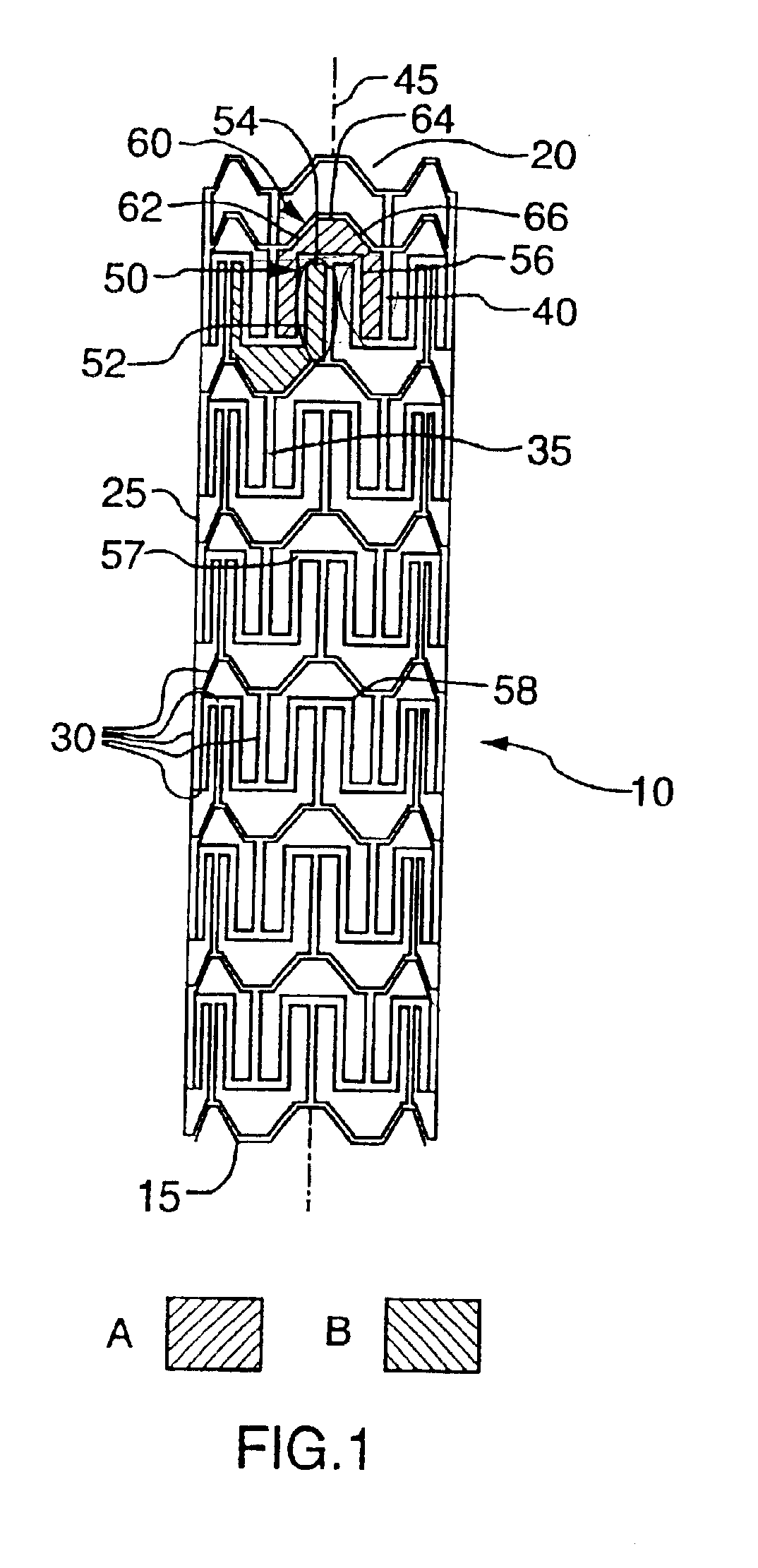
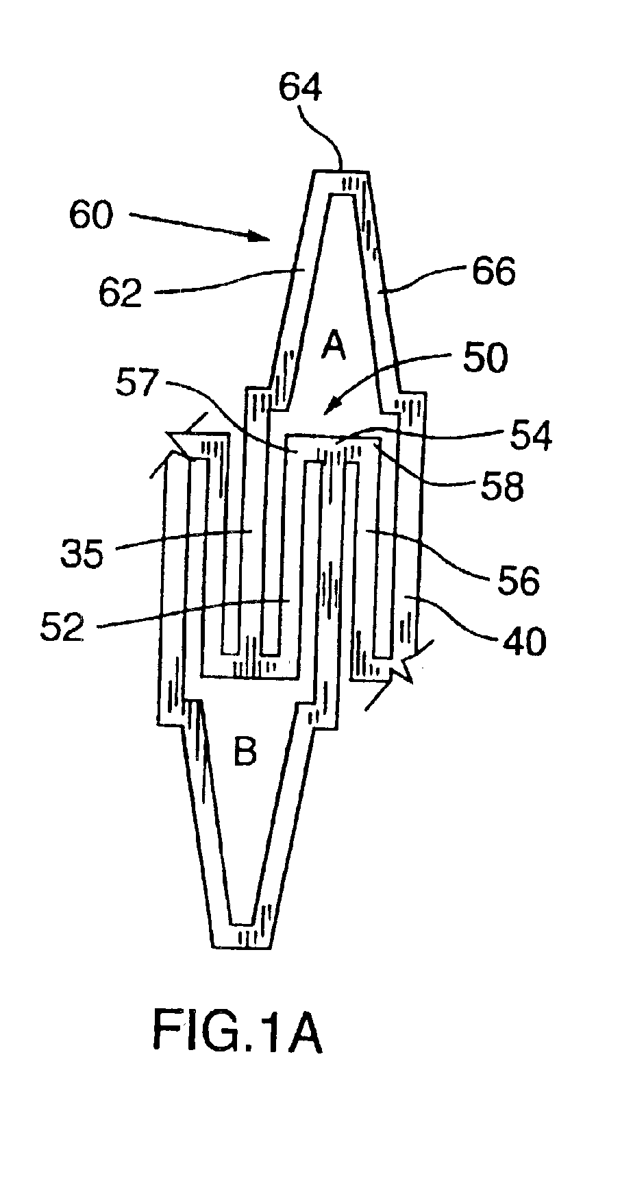
[0062]With reference to FIG. 1, there is illustrated a stent 10. Stent 10 comprises a proximal end 15 and a distal end 20. Stent further comprises a tubular wall 25 disposed between proximal end 15 and distal end 20. As illustrated, tubular wall 25 is porous. The porosity of tubular wall 25 is defined by a plurality of intersecting members 30. Intersecting members 30 define a first repeating pattern designated A in FIG. 1.
[0063]As illustrated and with further reference to FIG. 1A, repeating pattern A is a polygon comprising a pair of side walls 35,40. Side walls 35,40 are substantially parallel to a longitudinal axis 45 of stent 10 and thus side walls 35,40 may be considered to be longitudinal struts (indeed with reference to each of the drawings, side walls may also be considered to be longitudinal struts). Side walls 35,40 are connected by a concave-shaped wall 50 and a convex-shaped wall 60.
[0064]As illustrated, concave-shaped wall 50 is made up of a trio of segments 52,54,56. In...
PUM
Abstract
An expandable stent comprising a proximal end and a distal end in communication with one another and a tubular wall disposed between the proximal end and the distal end. The tubular wall has a longitudinal axis and a porous surface defined by a plurality of intersecting members comprising a series of longitudinal struts disposed substantially parallel to the longitudinal axis of the stent. Each longitudinal strut in the series comprises flexure means for substantially complementary extension and compression of a diametrically opposed pair of the longitudinal struts upon flexure of the stent. The stent is expandable from a first, contracted position to a second, expanded position upon the application of a radially outward force on the stent. The provision of such flexure means in the series of struts leads to a very desirable balance of lateral flexibility of the unexpanded stent and radial rigidity of the expanded stent.
Description
TECHNICAL FIELD[0001]This application is a continuation of U.S. patent application Ser. No. 10 / 073,277, filed Feb. 13, 2002, which is a continuation of U.S. patent application Ser. No. 09 / 672,767, filed Sep. 29, 2000, now U.S. Pat. No. 6,375,677, issued Apr. 23, 2002, which is a continuation of U.S. patent application Ser. No. 09 / 142,508, filed Feb. 16, 1999, now U.S. Pat. No. 6,217,608, issued Apr. 17, 2001, which is a U.S. National Phase under 35 U.S.C. §371 of PCT / CA97 / 00151, filed Mar. 5, 1997 (designating the U.S.; and which published in English in WO 97 / 32543 on Sep. 12, 1997), which claims the benefit of Canadian Patent No. 2,171,047, filed Mar. 5, 1996, Canadian Patent No. 2,175,722, filed May 3, 1996, Canadian Patent No. 2,185,740, filed Sep. 17, 1996, and Canadian Patent No. 2,192,520, filed Dec. 10, 1996. The contents of all of the U.S. Patent Applications are incorporated herein by reference in their entirety.BACKGROUND ART[0002]Stents are generally known. Indeed, the te...
Claims
Application Information
Patent Timeline
Application Date:The date an application was filed.
Publication Date:The date a patent or application was officially published.
First Publication Date:The earliest publication date of a patent with the same application number.
Issue Date:Publication date of the patent grant document.
PCT Entry Date:The Entry date of PCT National Phase.
Estimated Expiry Date:The statutory expiry date of a patent right according to the Patent Law, and it is the longest term of protection that the patent right can achieve without the termination of the patent right due to other reasons(Term extension factor has been taken into account ).
Invalid Date:Actual expiry date is based on effective date or publication date of legal transaction data of invalid patent.

