Chair stacker apparatus

a stacking chair and chair technology, applied in the field of chairs, can solve the problems of inadvertent scratching or marring of the legs of the stackable chair, and achieve the effect of facilitating the creation of an upright vertical stack of chairs

Inactive Publication Date: 2005-03-15
DOREL HOME FURNISHINGS INC
View PDF31 Cites 50 Cited by
  • Summary
  • Abstract
  • Description
  • Claims
  • Application Information

AI Technical Summary

Benefits of technology

In an illustrative embodiment, a leg cap including a guide bumper is coupled to a lower end of each leg. A stacker bumper is coupled to an upper end of each leg; The guide and stacker bumpers on each leg are adapted to engage a companion adjacent leg of the underlying chair to maintain those legs in spaced-apart parallel relation to one another when the chair is stacked on the underlying chair to facilitate creation of an upright vertical stack of chairs.

Problems solved by technology

The legs of stackable chairs can be marred or scratch inadvertently if the legs of one chair are allowed to contact the legs of another chair in a stack of chairs.

Method used


Image

  • Chair stacker apparatus
  • Chair stacker apparatus
  • Chair stacker apparatus

Examples


Embodiment Construction

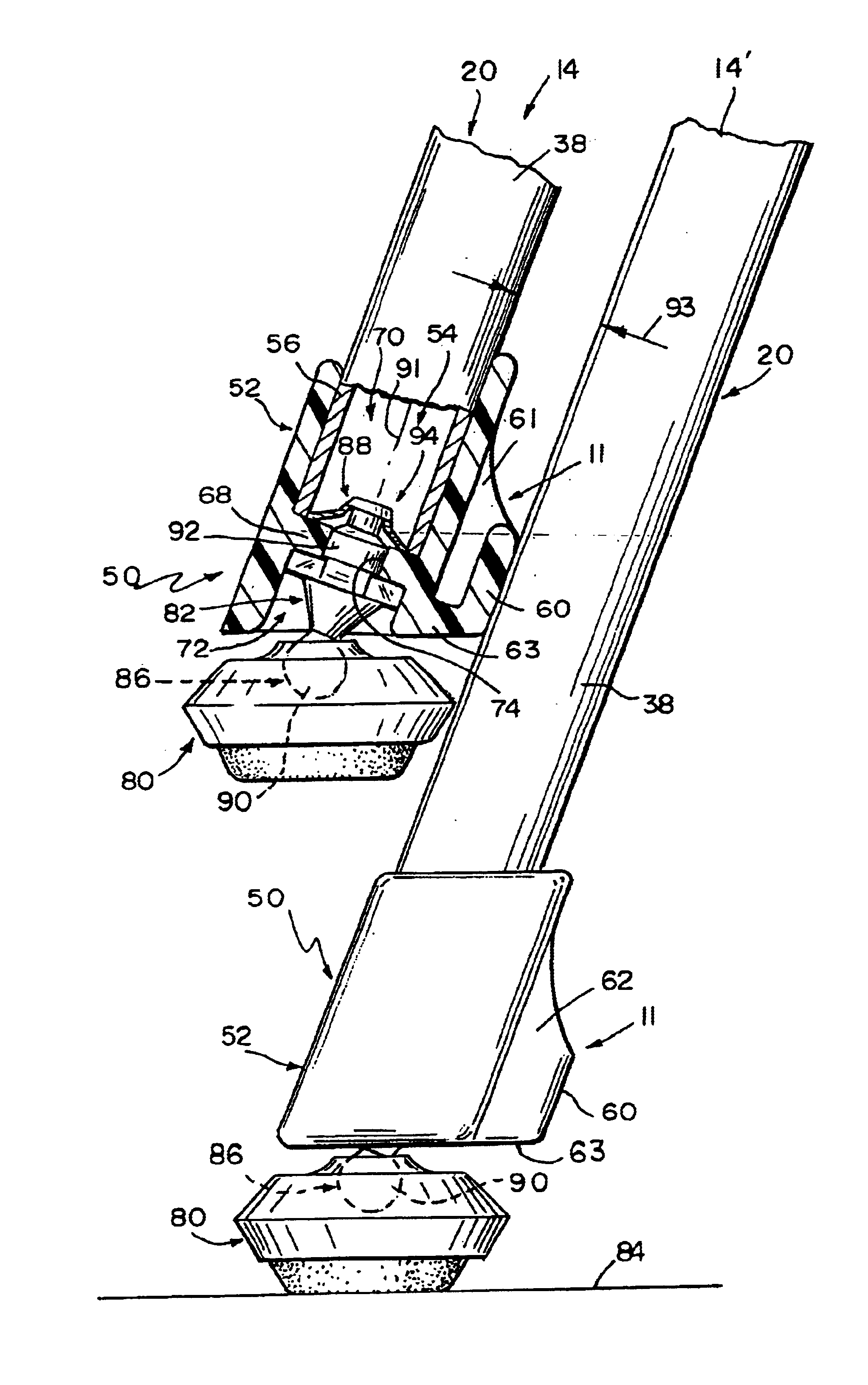
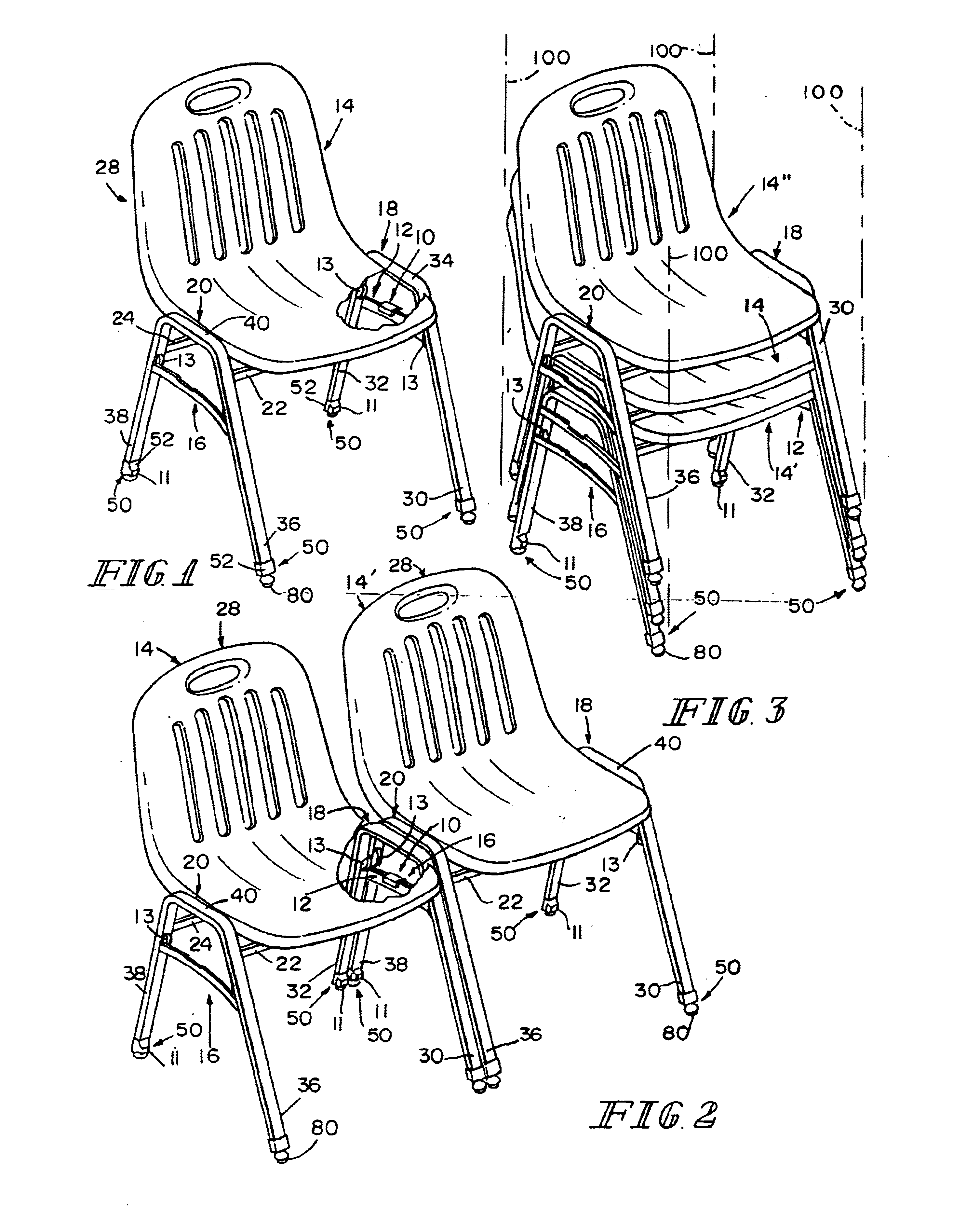
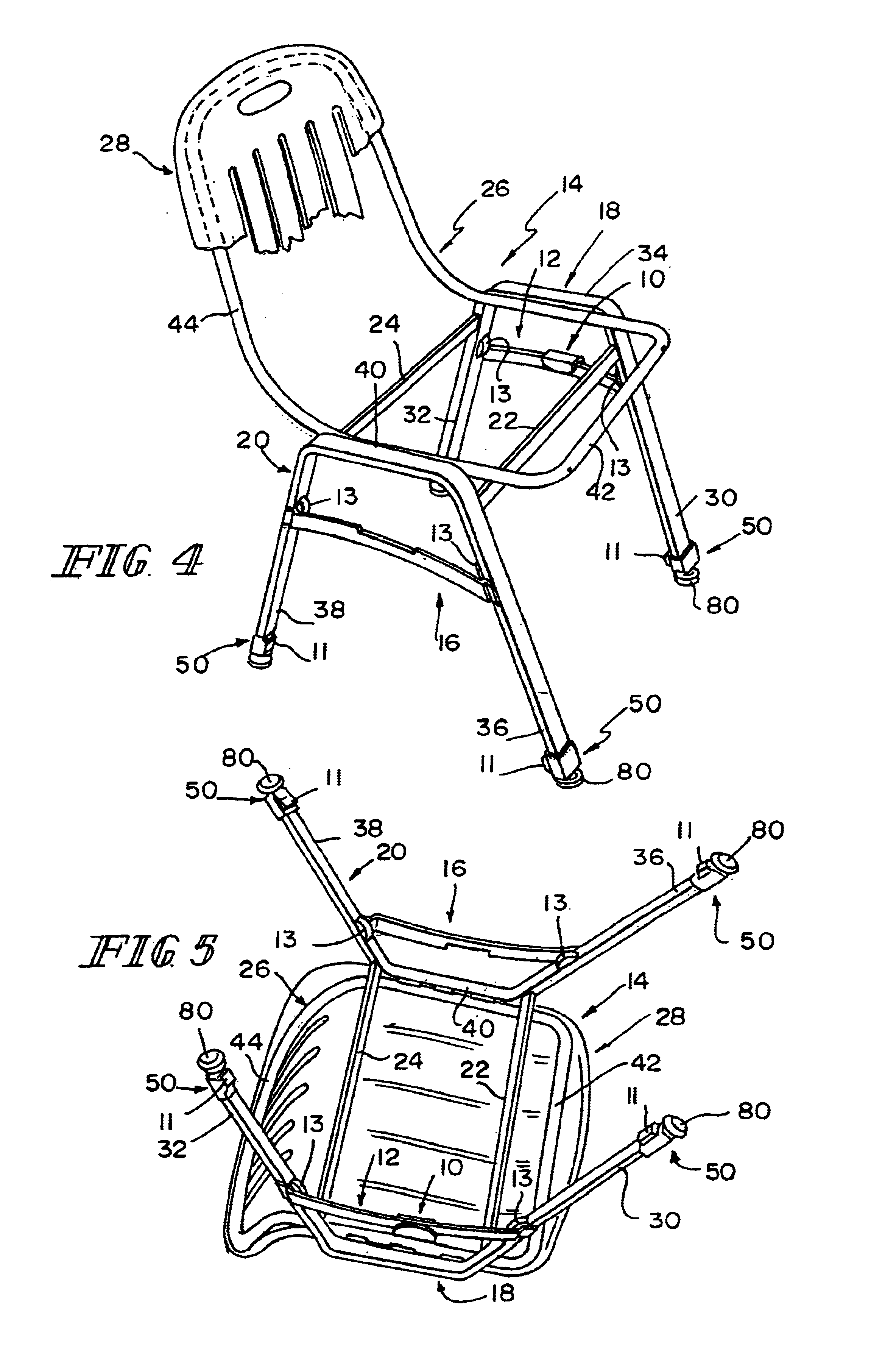
A gang flange 10 is coupled to a first cross bar 12 included in a chair 14 as shown in FIG. 1. Chair 14 also includes a second cross bar 16 arranged to lie in spaced-apart relation to first cross bar 12. Gang flange 10 on chair 14 is arranged and configured to mate with a second cross bar 16 on an adjacent chair 14′ to “gang” chairs 14 and 14′ together as shown, for example, in FIG. 2. Using gang flange 10, chairs 14 and 14′ can be ganged to one another (as suggested in FIGS. 2 and 6) or stacked on one another (as shown in FIG. 3) easily.

Chairs 14, 14′, and 14″ are also configured to be stacked as shown, for example, in FIGS. 3 and 14. Guide bumpers 11 and stacker bumpers 13 are provided to separate one chair from another when the chairs are stacked for storage.

Chair 14 includes a first leg unit 18 carrying two guide bumpers 11, first cross bar 12, and two stacker bumpers 13 (as shown, for example, in FIGS. 1, 4, and 5). Chair 14 also includes a second leg unit 20 carrying two more ...


PUM


Abstract

A chair includes a seat and a seat frame including several legs. Bumpers are coupled to the legs and arranged to separate one chair from an underlying chair in a stack of chairs.

Description

BACKGROUND AND SUMMARYThe present disclosure relates to chairs, and particularly to stackable and gangable chairs. More particularly, the present disclosure relates to apparatus for stacking chairs.Some chairs are configured to be stacked on top of one another to conserve storage space. The legs of stackable chairs can be marred or scratch inadvertently if the legs of one chair are allowed to contact the legs of another chair in a stack of chairs.According to the present disclosure, a chair includes a seat and a seat frame including several legs. Bumpers are coupled to the legs and arranged to separate the legs of the chair from the legs of an underlying chair in a stack of chairs.In an illustrative embodiment, a leg cap including a guide bumper is coupled to a lower end of each leg. A stacker bumper is coupled to an upper end of each leg; The guide and stacker bumpers on each leg are adapted to engage a companion adjacent leg of the underlying chair to maintain those legs in spaced...

Claims


Application Information

Patent Timeline
Patent Type & Authority Patents(United States)
IPC IPC(8): A47C3/04A47C3/00A47C1/124
CPCA47C1/124A47C3/04A47C7/002Y10T16/209Y10T16/21Y10T16/216
Inventor MENDENHALL, ANDREW B.ANDREWS, JASON S.TURNER, DENNIS M.
Owner DOREL HOME FURNISHINGS INC
Why Eureka
Try Eureka