Combination lock capable of being opened by a key

a combination lock and key technology, applied in the field of combination locks, can solve the problems of inability to manufacture, difficult to loosen sealing caps, and inability to disclose integral combination locks and padlocks,

Inactive Publication Date: 2005-06-14
LIN CHU PAO FENG
View PDF10 Cites 48 Cited by
  • Summary
  • Abstract
  • Description
  • Claims
  • Application Information

AI Technical Summary

Benefits of technology

[0005]It is an object of the present invention to provide a combination lock, comprising a substantially parallelepiped body including an elongated shackle receiving bore, a shallow shackle receiving hole on a top of the body opposite the bore, a plurality of parallel dial receiving slots crossed the bore, a plurality of ridged in an inner wall of the bore, each ridge being adjacent the dial receiving slot, a longitudinal groove adjacent and parallel with the bore, a channel perpendicular to the groove, a key hole perpendicular to the channel, a cavity recessed from the shackle receiving hole and aligned with the key hole, the cavity including a lengthwise ledge, a seat at both sides of the cavity, and a seat cover rested on the seat; a housing including mated upper and lower panels each including a dial receiving recess, a first half-circular indentation aligned with the bore, a second half-circular indentation aligned with the shackle receiving hole, and a third half-circular indentation aligned with the key hole; a plurality of separate and independent rotatable dials mounted at the dial receiving slots, each dial including a plurality of slits on an inner surface and a plurality of numeral panels on an outer surface; a plurality of tumbler sleeves each rotatably provided in the inner surface of the dial, each tumbler sleeve including a plurality of radial fins and a substantially flat member around an outer surface wherein the number of the fins is less than that of the slits by one; a resilient element including a plurality of pegs mounted in the dial receiving slots wherein each peg is forced to engage with the outer surface of the dial; a washer tightly fitted on a mouth of the bore for preventing any external contaminants from reaching inside; an elongated key lock assembly mounted in the key hole, the key lock assembly including an inward projection having a cam section; a sliding seat fitted onto the groove and the channel, the sliding seat including an opening aligned with the key hole so as to receive the projection and cause the sliding seat to be slidable by turning the key lock assembly, an aperture in communication with the opening and having a diameter smaller than that of the opening, and a plurality of legs each aligned with a portion of the body between two adjacent dial receiving slots, each leg having a substantially arcuate member; a U-shaped shackle including a short leg having its end insertable into the shackle receiving hole, and a long leg having its end inserted into a bottom of the bore and being allowed to advanced axially a distance along the bore in a locking or unlocking operation; a push button disposed in the cavity being proximate the shackle receiving hole, the push button including a toothed section around an inner surface and two opposite indentations on an outer surface; and a spring biased locking pin including a toothed member around an end, a plurality of equally spaced raised portions adjacent the toothed member with a passage formed between any two adjacent raised portions and the ledge being fitted in one of the passages, a plurality of slopes each at the raised portion, a shaft aligned with the aperture, and a spring put on the shaft, wherein the ridge is inserted into a valley between two adjacent fins of each tumbler sleeve for locking with the arcuate members being urged against the flat member; the dials are arranged into a predetermined numeral sequence by disengaging the arcuate members from the fins for unlocking; insert a key into the key hole to rotate the projection for sliding the sliding seat and disengaging the arcuate members from the fins; in response to unlocking the lock, use a tool to press the push button to advance the push button and the locking pin inside until the passage is clear from the ledge, insert a pointed portion of the tool into at least one of the indentations, rotate the push button to engage the projection with the slope, further press the push button to advance the locking pin inside and matingly engage the toothed member with the toothed section, and rotate the push button and the locking pin until the ledge inserts into the passage with the shaft being entered into the aperture for locking the sliding seat during an operation of inhibiting the lock from being opened by the key; and responsive to unlocking the lock, pull the long leg by a plurality of steps wherein in each step the fins of the tumbler sleeve are completely withdrawn from the slits and are locked by one adjacent ridge, thereby enabling a change of one numeral of a predetermined combination.

Problems solved by technology

While the patent may be suitable for the particular purpose to which it addresses, it still has the drawbacks of being weak of certain components, possible loosening of sealing cap, and difficult of manufacturing due to excessive internal components.
Unfortunately, an integral combination lock and padlock has not been disclosed as far as the present inventor is aware.

Method used


Image

  • Combination lock capable of being opened by a key
  • Combination lock capable of being opened by a key
  • Combination lock capable of being opened by a key

Examples


Embodiment Construction

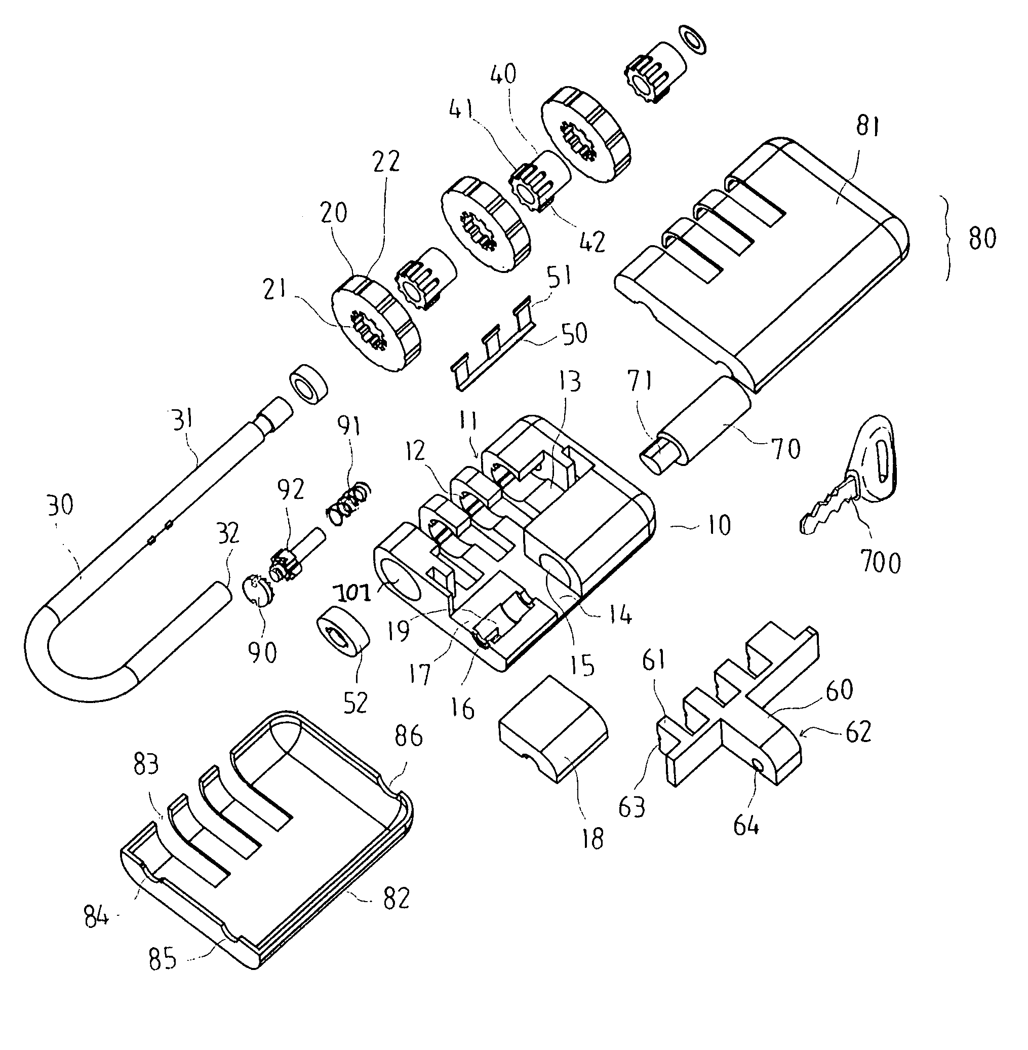
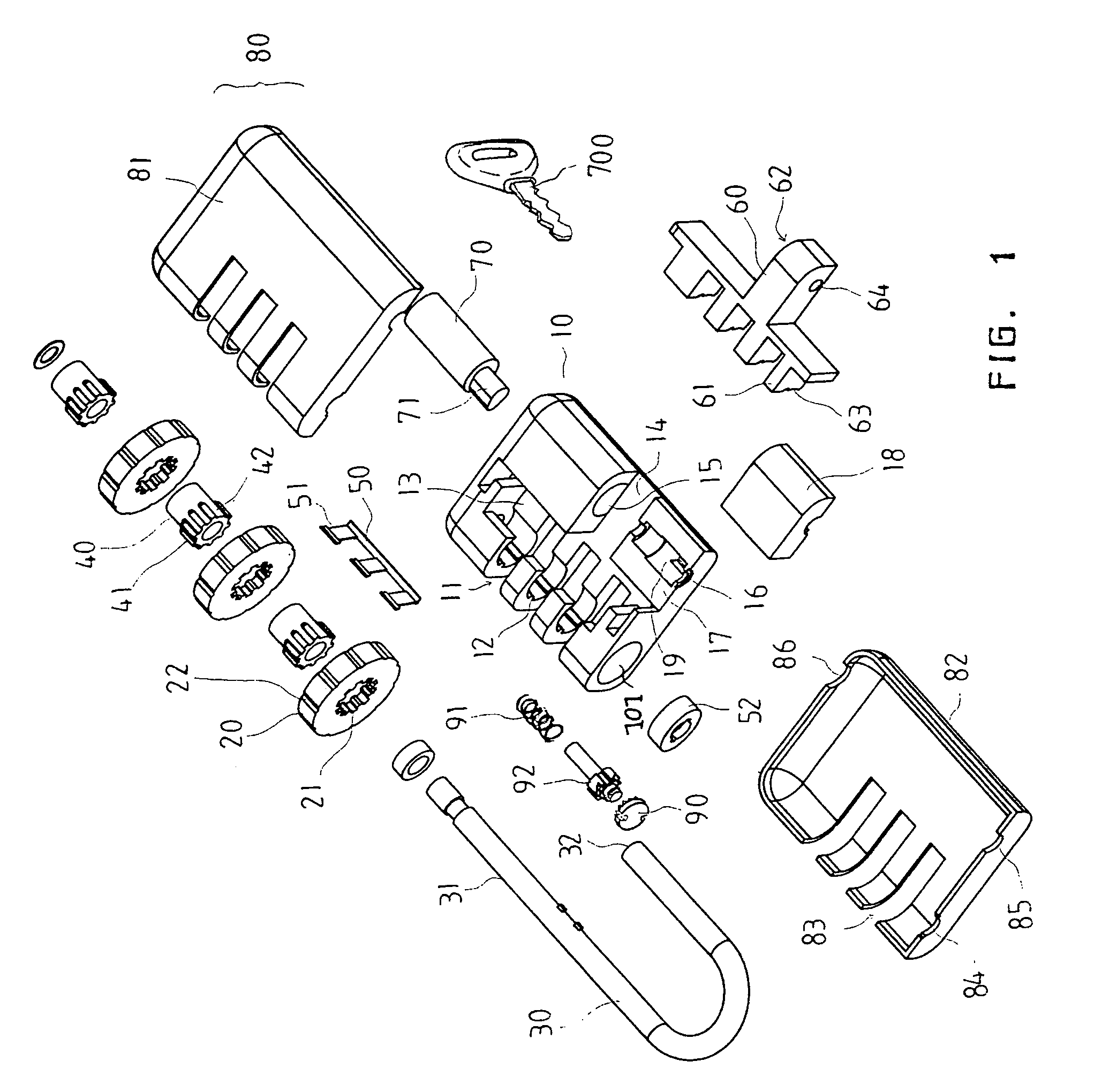
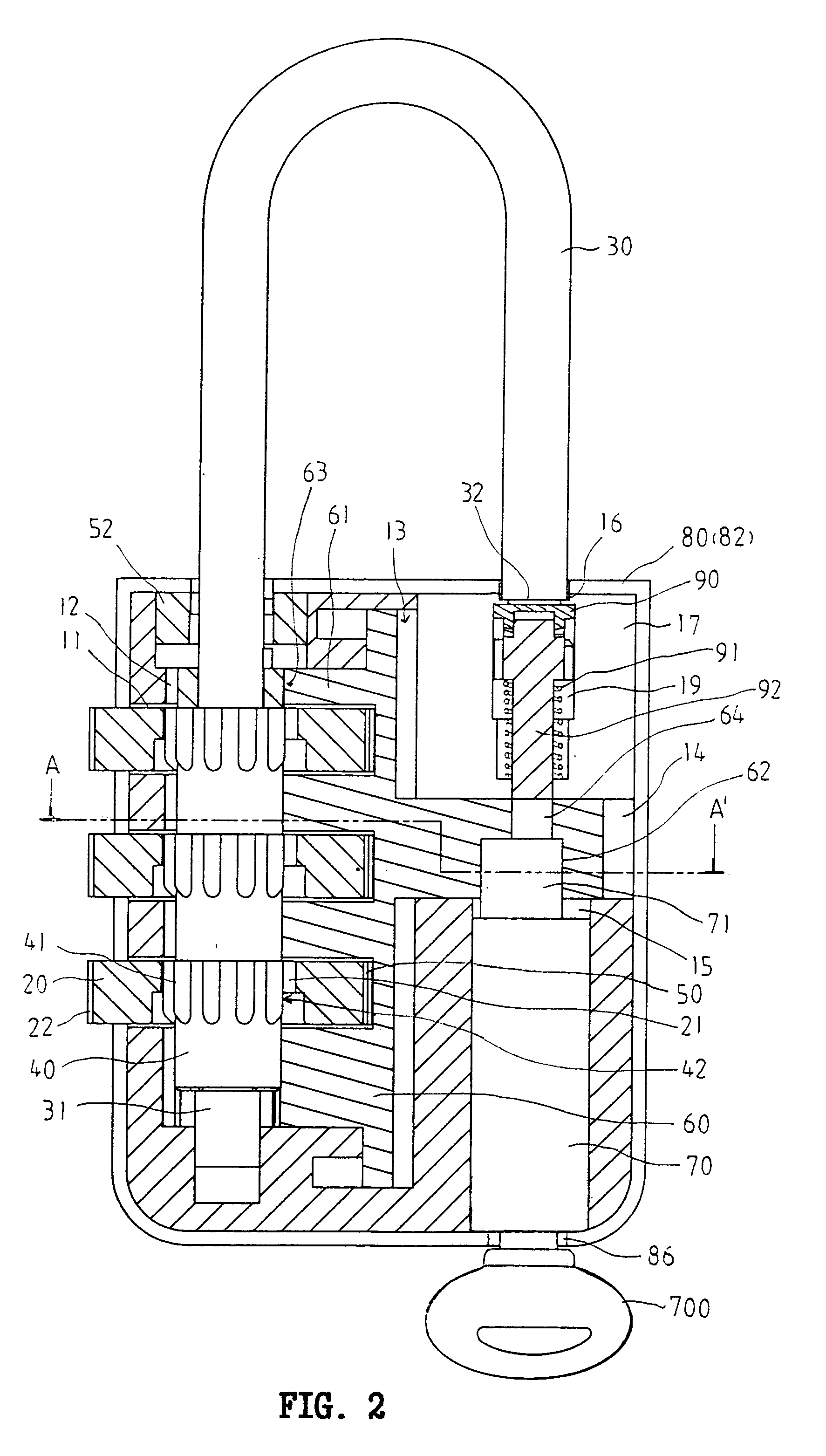
[0023]Referring to FIGS. 1 to 19, a combination lock constructed in accordance with the invention is shown. The combination lock comprises a substantially parallelepiped body 10 including an elongated shackle receiving bore 101 extended from a top of the body 10 almost to a bottom thereof, a shallow shackle receiving hole 16 on the top of the body 10 opposite the bore 101, three parallel dial receiving slots 11 crossed the bore 101, a ridge 12 in an inner wall of the bore 101 adjacent each slot 11, a longitudinal groove 13 adjacent and parallel with the bore 101, a channel 14 perpendicular to the groove 13, a key hole 15 perpendicular to the channel 14, a cavity 19 recessed from the shackle receiving hole 16 and aligned with the key hole 15, the cavity 19 including a lengthwise ledge 191 having a slope 192 at its inner end, a seat 17 at both sides of the cavity 19, and a seat cover 18 rested on the seat 17; a housing 80 including mated upper and lower panels 81 and 82 each including...


PUM


Abstract

Disclosed is a combination lock wherein responsive to unlocking the lock, use a tool to press the push button to advance a push button and a locking pin inside until a passage is clear from a ledge, insert a pointed portion of the tool into an indentation on a push button, rotate the push button to engage a projection with a tooth, further press the push button to advance a locking pin inside and matingly engage the push button with the locking pin, and rotate the push button and the locking pin until the ledge inserts into the passage with a spring biased pin being entered into an aperture of a sliding seat for locking during an operation of inhibiting the lock from being opened by a key.

Description

BACKGROUND OF THE INVENTION[0001]1. Field of the Invention[0002]The present invention relates to combination locks and more particularly to a combination lock which can be opened by an authorized person by means of a key in addition to the typical opening by arranging dials into a numeral sequence desired by the user. Further, the authorization can be inhibited.[0003]2. Description of Related Art[0004]Combination locks are well known. One particular type of combination lock is disclosed in U.S. Pat. No. 5,715,709. While the patent may be suitable for the particular purpose to which it addresses, it still has the drawbacks of being weak of certain components, possible loosening of sealing cap, and difficult of manufacturing due to excessive internal components. Moreover, it is known that a padlock can only be opened by a key. Unfortunately, an integral combination lock and padlock has not been disclosed as far as the present inventor is aware. Further, it is understood that a user ma...

Claims


Application Information

Patent Timeline
Patent Type & Authority Patents(United States)
IPC IPC(8): E05B37/02E05B37/00E05B67/00E05B67/24E05B63/00
CPCE05B37/025E05B67/24E05B37/0034Y10S70/71E05B63/0065E05B37/0058Y10T70/415Y10T70/424Y10T70/7141Y10T70/7345
Inventor LIN, CHU PAO-FENG
Owner LIN CHU PAO FENG
Why Eureka
Try Eureka