Collapsible container

Inactive Publication Date: 2005-07-19
REHRIG PACIFIC CO INC
View PDF77 Cites 94 Cited by
  • Summary
  • Abstract
  • Description
  • Claims
  • Application Information

AI Technical Summary

Benefits of technology

[0006]It is an object of the present invention to provide a col

Problems solved by technology

However, for an assembled container during use, this corner system results in a less rigid container due to the corners being subjected to torsional and other bending forces during use.
Furth

Method used


Image

  • Collapsible container
  • Collapsible container
  • Collapsible container

Examples


second embodiment

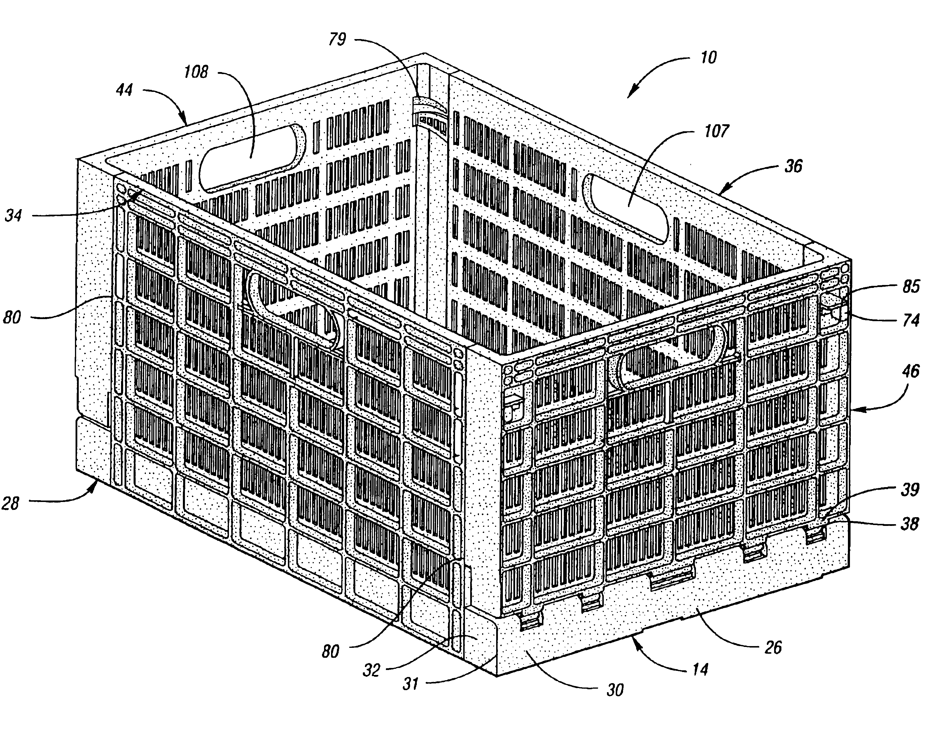
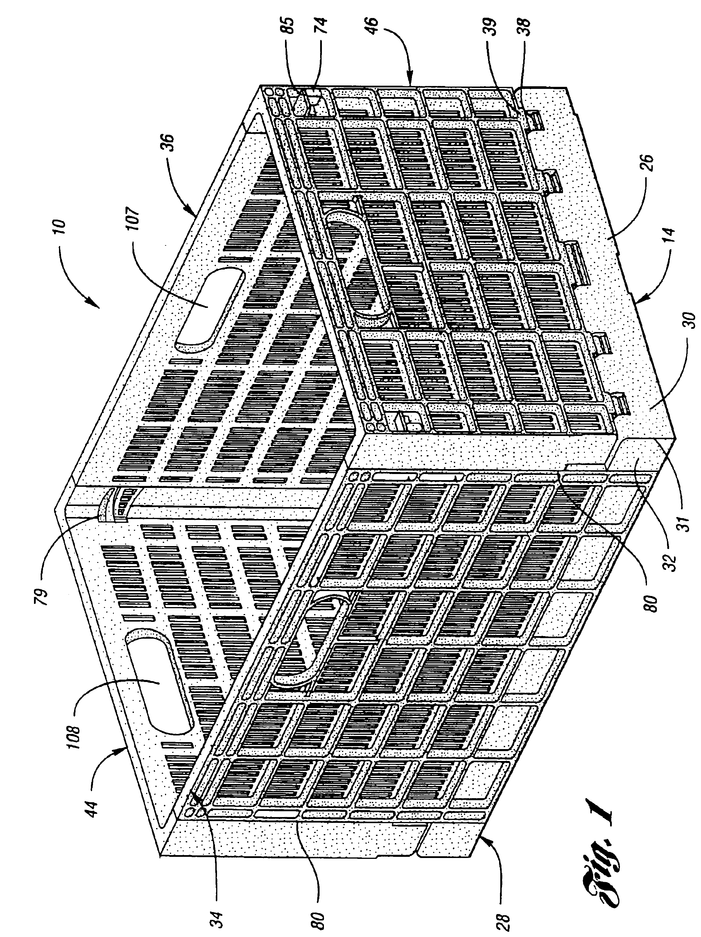
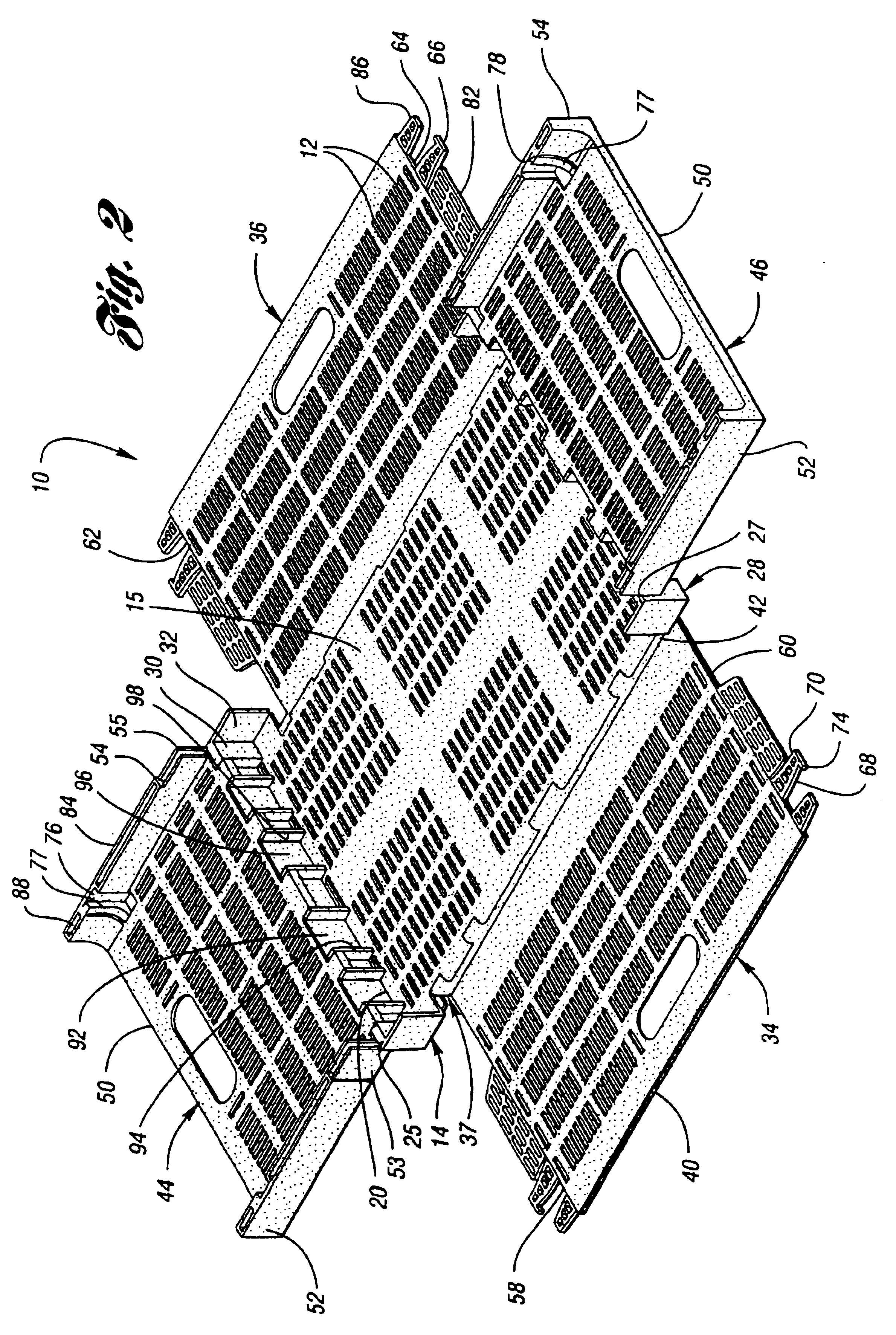
[0059]With reference to FIGS. 7-9 of the drawings, shown therein is a collapsible container according to the present invention. Container 110 is shown in FIG. 7 in an assembled orientation. Like the previous embodiment, container 110 is also capable of being collapsed into each of an inwardly folded position and an outwardly folded position in the manner illustrated in FIG. 2 and 3. Container 110 includes a plurality of slots 112 formed therein for promoting circulation of air and other gases to keep the contents of the container fresh. Further included is a base 114 which is discussed further herein in association with FIGS. 8-9. Container 110 also includes a pair of opposed side walls 134 and 136, as well as a pair of opposed end walls 144 and 146 with flanges 152,154. Each side wall (134,136) and end wall (144, 146) is pivotably attached to base 114.

first embodiment

[0060]FIG. 8 illustrates the base 114 of container 110 shown in FIG. 7. Base 114 includes a bottom panel 115 which is rectangular in shape and has opposing side edges 116 and 118, and further includes opposing end edges 120 and 122. A pair of opposed upstanding flanges 124 and 126 is provided and each is formed perpendicular to bottom panel 115. Each upstanding flange 124 and 126 defines an upper side edge 125 and 127, respectively. As with the first embodiment previously disclosed herein, each side wall (134, 136) is pivotally hinged with respect to base 114 at a corresponding side edge (116, 118), while each end wall (144,146) is pivotally hinged with respect to base 114 at a corresponding end upper edge (125, 127). Thus each end wall (144,146) is pivotally attached to base 114 at a distance remote from base 114. Particularly, the distance is defined by the height of upstanding flanges 124 and 126.

[0061]With regard to hinging systems of container 110, shown in association with bas...


PUM


Abstract

A collapsible container orientable between assembled and collapsed positions having a base, a pair of side walls and a pair of end walls. The base has a pair of opposing upstanding end flanges integral thereto defining a corner line at each end and a side face member perpendicular. A pair of opposing side edges lie in a plane parallel to and spaced inward from an adjacent co-planar pair of side face members and extending therebetween. Opposing side walls are pivotably attached to one of the opposing side edges, forming an extension of the base when the container is in assembled. Each side wall has a latch member at each lateral edge having upper and lower curved surfaces and a tooth at its distal end. Each end wall has a pair of flanges with an opening sized to slidingly receive a latching member in the assembled state and is securely held by a living hinge. The container is adapted to being nestable when in the collapsed position.

Description

[0001]This is a continuation of application Ser. No. 09 / 578,766 filed on May 25, 2000 now U.S. Pat. No. 6,209,742, which is a continuation of application Ser. No. 09 / 412,095 filed Oct. 4, 1999 now U.S. Pat. No. 6,098,827 issued Aug. 8, 2000, which is a continuation of U.S. Ser. No. 08 / 994,061, filed Dec. 19, 1997, now U.S. Pat. No. 6,015,056, issued Jan. 18, 2000.TECHNICAL FIELD[0002]This invention relates to a multi-purposed collapsible container for the storage and transport of produce items and other goods.BACKGROUND ART[0003]Collapsible containers and crates are commonly used to transport and store a variety of items. Such crates are typically formed of injection molded plastic and are frequently adapted to receive perishable food items, such as produce. When assembled, such containers are rectangular in shape and have a flat base surrounded by four upstanding side panels which are joined to the flat base. When the containers are not in use, the collapsible feature of the contai...

Claims


Application Information

Patent Timeline
IPC IPC(8): A45C7/00
CPCA45C7/0036B65D11/1833
Inventor OVERHOLT, TRENTON M.APPS, WILLIAM PATRICKKOEFELDA, GERALD R.
Owner REHRIG PACIFIC CO INC
Why Eureka
Try Eureka