Stapler anvil

a technology of stapler and stapler, which is applied in the field of staplers, can solve the problems of affecting the quality of staplers, so as to facilitate staple removal and prevent staple jamming

Inactive Publication Date: 2005-08-09
ACCO BRANDS USA LLC
View PDF23 Cites 586 Cited by
  • Summary
  • Abstract
  • Description
  • Claims
  • Application Information

AI Technical Summary

Benefits of technology

This patent describes an improvement to a stapler's design called the anvil. It helps with faster and more efficient stapling of up to 150 sheets per staple. By keeping the staples organized and aligned properly, it reduces frustration during stapling and makes the final result look better. Overall, this innovation improves the performance and appearance of staplers.

Problems solved by technology

The technical problem addressed in this patent text relates to the limited ability of manual staplers to handle varying amounts of paper without becoming blocked or unable to fully drive the staple into place. This requires users to switch between different sized staples depending on the amount of material they require to securely attach multiple layers of paper.

Method used


Image

  • Stapler anvil
  • Stapler anvil
  • Stapler anvil

Examples


Embodiment Construction

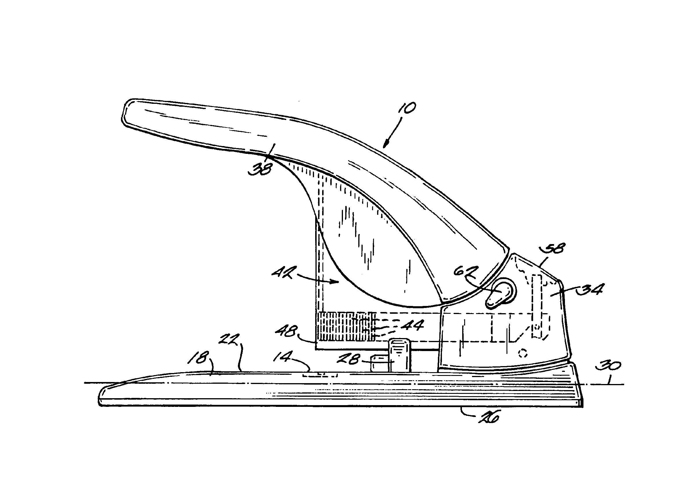
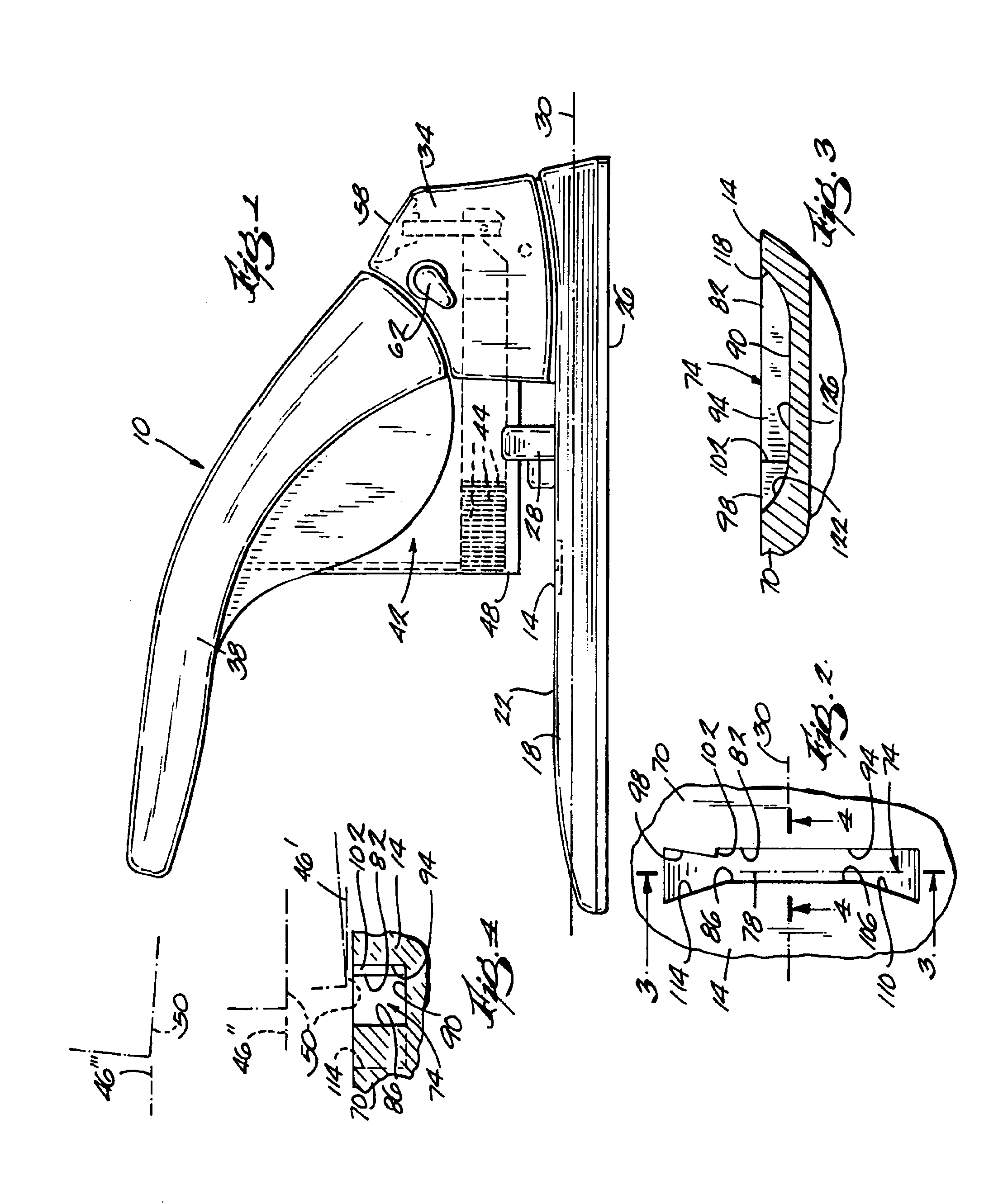
[0024]FIG. 1 illustrates a stapler 10 including an anvil 14 embodying the invention. The stapler 10 includes a base 18 having a top surface 22 and a bottom surface 26. The top surface 22 is configured to support a stack of sheets to be stapled. An adjustable paper guide 28 is mounted on the top surface 22. The bottom surface 26 is configured to support the stapler 10 on a support surface. The base 18 defines a longitudinal axis 30.

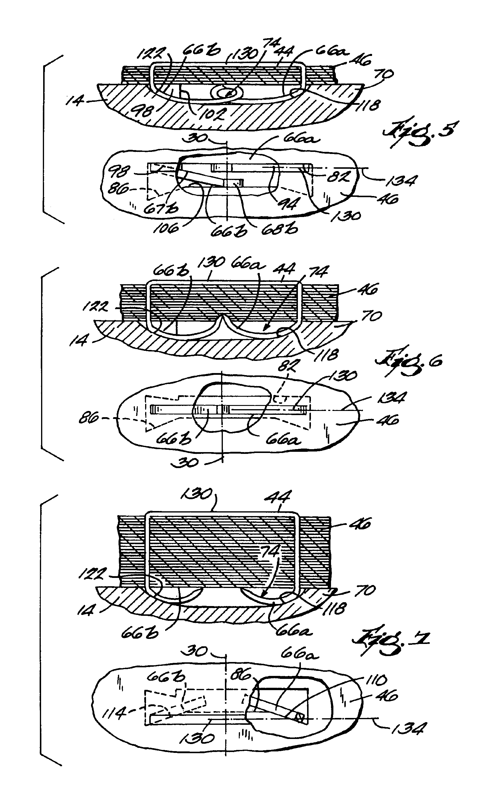
[0025]The base 18 includes an upper housing 34 that houses components of the stapling mechanism. A lever arm 38 is movably coupled (e.g., pivotally) to the base 18. A magazine assembly 42 is coupled with the upper housing 34 and the lever arm 38, and operates to discharge a staple 44 into a plurality of sheets 46 (see FIGS. 5-7) upon manual actuation of the lever arm 38. The magazine assembly 42 includes a magazine 48 that holds a row of staples 44. The magazine 48 includes a discharge opening (not shown) through which a staple 44 is discharged from the ma...


PUM


Abstract

A stapler anvil and method for clinching a staple is disclosed. The anvil includes a body having a well. The well has an axis extending between the legs of a staple and is defined by a first surface having a first portion along which the first leg of the staple is directed as the staple is being clinched, and a second portion extending substantially at an angle relative to the first portion to direct the second leg of the staple at least partially away from the axis as the staple is clinched. The well is further defined by a second surface spaced from the first surface. The second surface is configured to redirect the second leg of the staple at least partially back toward the axis after the second leg has been directed at least partially away from the axis by the second portion of the first surface.

Description


Claims


Application Information

Patent Timeline
Owner ACCO BRANDS USA LLC
Why Eureka
Try Eureka