Mechanism for ensuring bimetallic plate to be deformed without barrier

a technology of bimetallic plates and mechanical mechanisms, applied in the field of circuit breakers, can solve problems such as disasters

Inactive Publication Date: 2005-09-06
YU TSUNG MOU
View PDF9 Cites 16 Cited by
  • Summary
  • Abstract
  • Description
  • Claims
  • Application Information

AI Technical Summary

Problems solved by technology

However, if the fuse is not properly installed or an improper fuse is used, the overloading current does not melt the fuse and a disaster can occur.
Nevertheless, it is noted that in some cases, even when an overloading occurs, the bimetallic plate does not completely deform as desired and remains in contact with a terminal of the circuit so that sparks could be produced, causing disaster.

Method used


Image

  • Mechanism for ensuring bimetallic plate to be deformed without barrier
  • Mechanism for ensuring bimetallic plate to be deformed without barrier
  • Mechanism for ensuring bimetallic plate to be deformed without barrier

Examples


Embodiment Construction

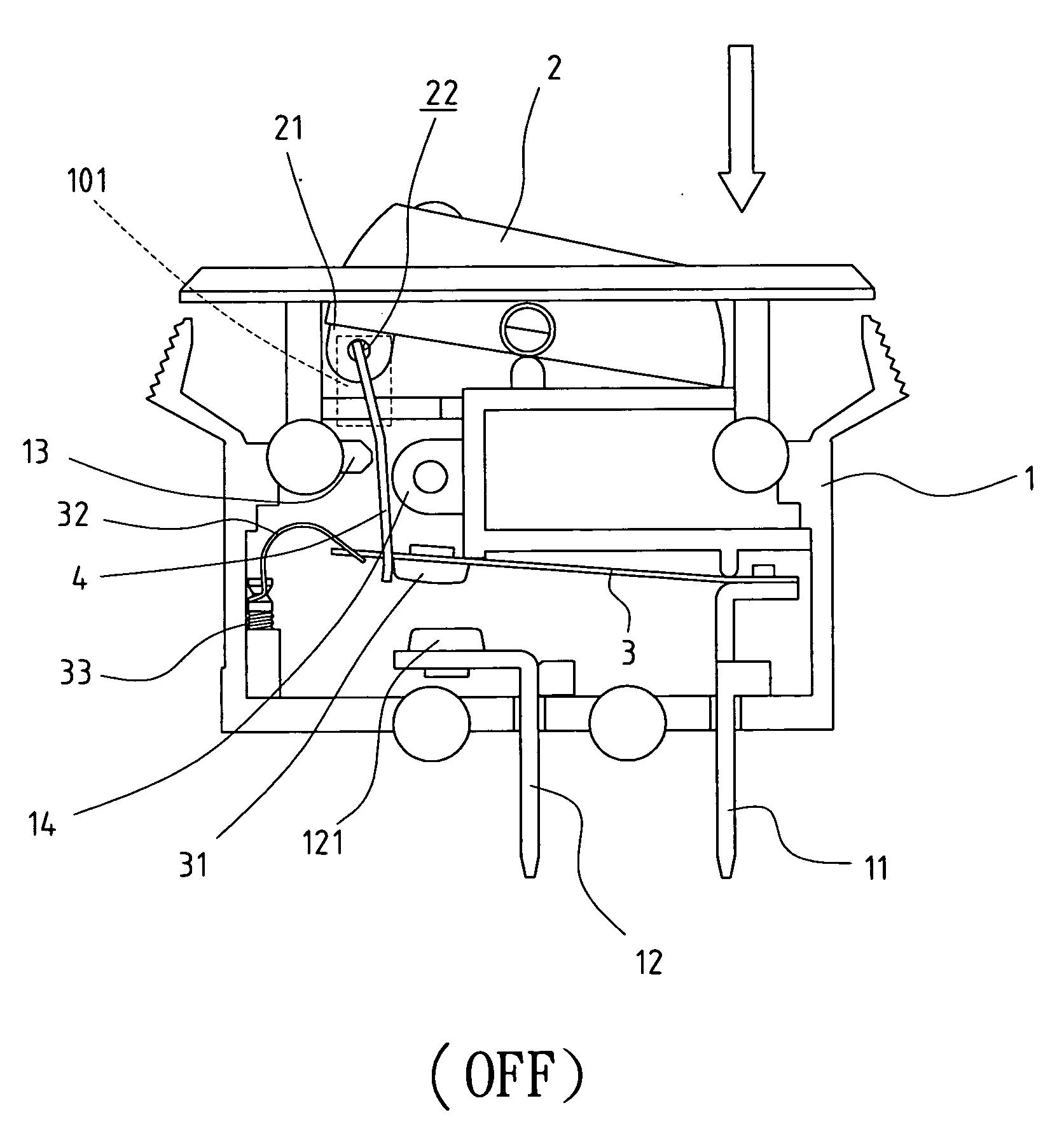
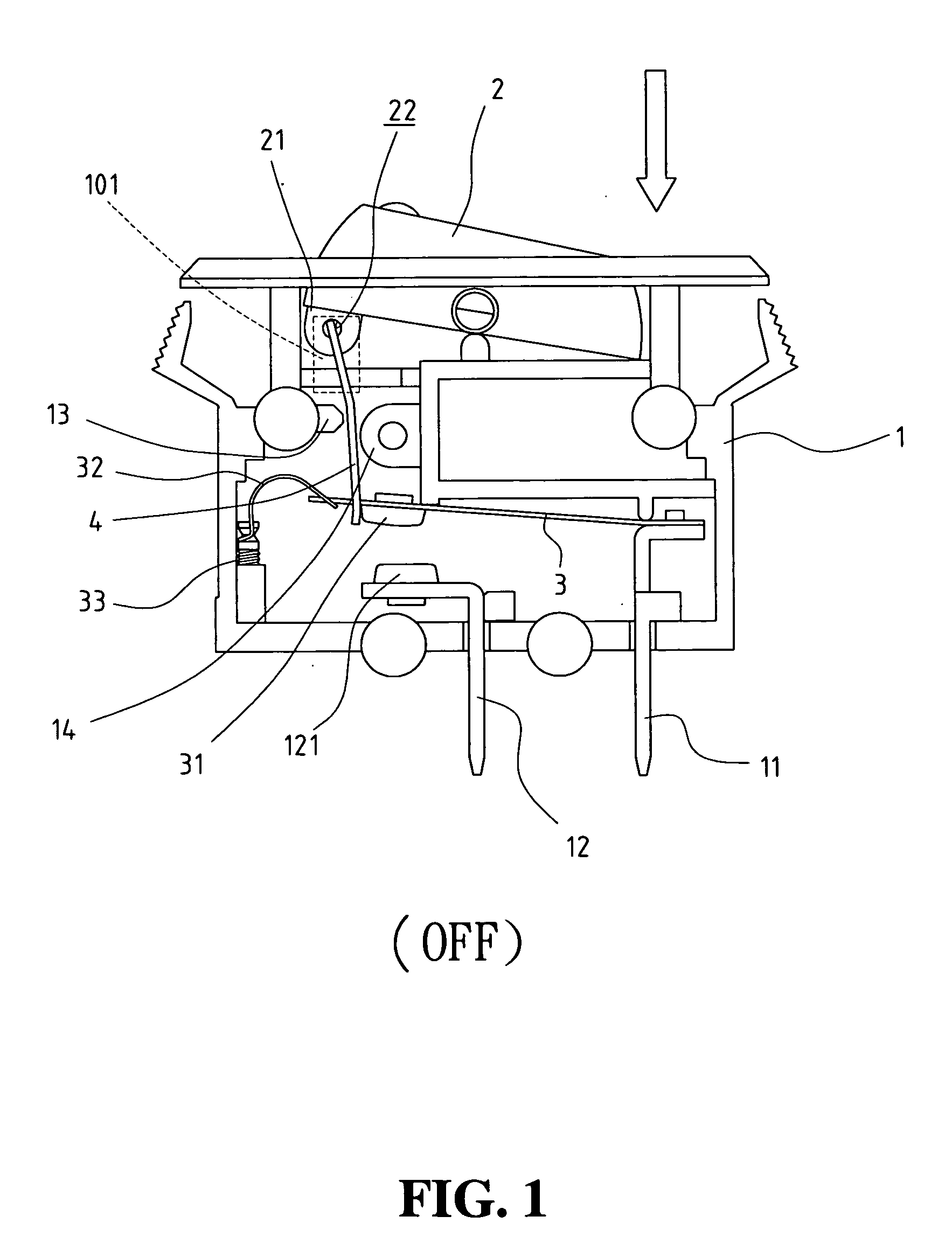
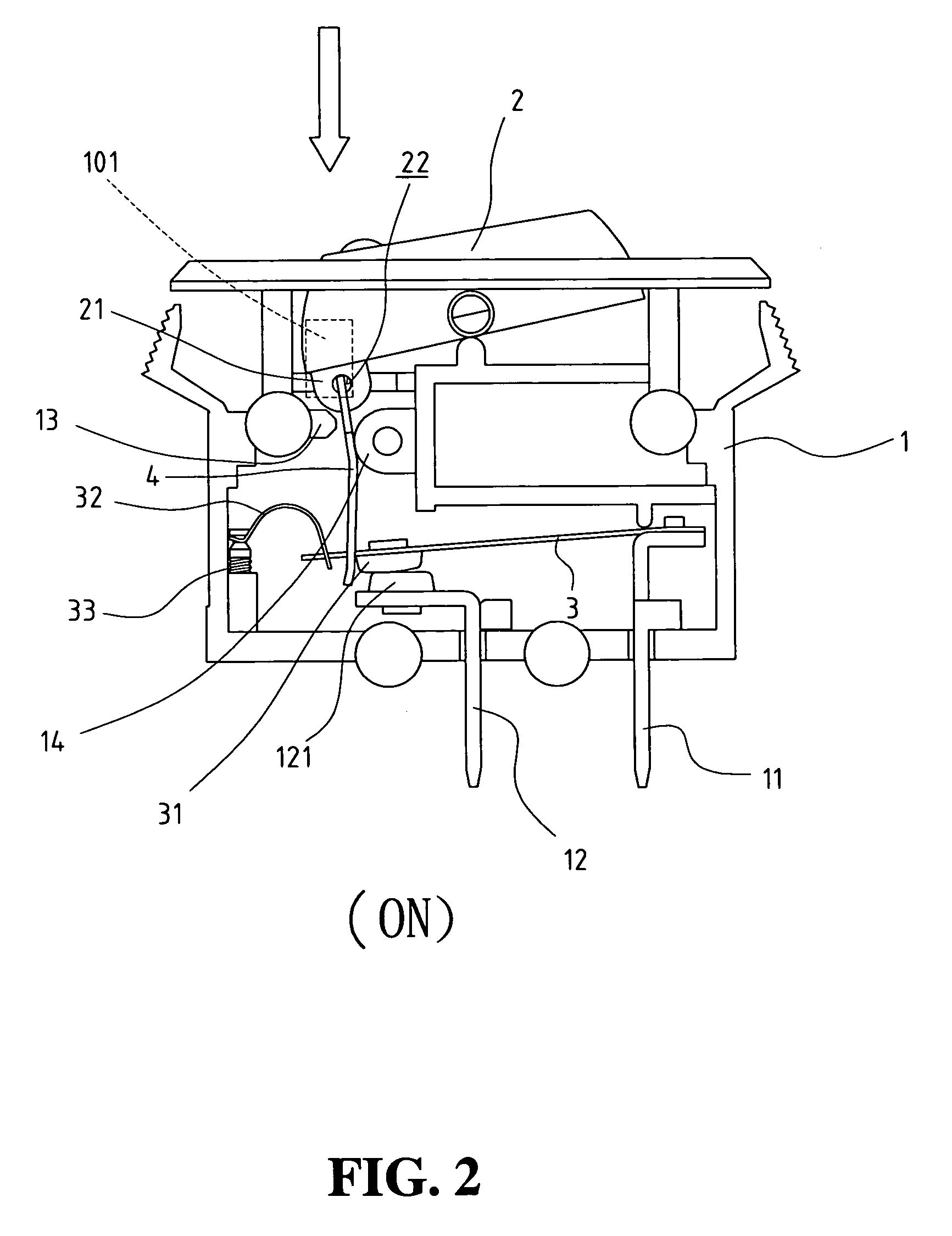
[0017]Referring to the drawings and in particular FIGS. 1, 2, 4, and 5, a circuit breaker in accordance with the present invention comprises a case 1 having an open top. A pushbutton 2 is pivotally connected between a front wall 10 and a rear wall of the case 1. The pushbutton 2 includes an extension 21 projecting from an underside thereof at an “ON” end of the pushbutton 2. The extension 21 has a hole 22 defined therethrough. A first terminal 11 and a second terminal 12 each have an end located in the case 1 and the other ends respectively extend through a bottom of the case 1. A first end of a bimetallic plate 3 is fixedly connected to the first terminal 11. A first contact point 31 is connected to an underside of a second end of the bimetallic plate 3. A second contact point 121 is connected to the second terminal 12 and located beneath the first contact point 31. As can be seen from FIG. 5, the bimetallic plate 3 is a long strip member which may be deformed when the circuit brea...


PUM


Abstract

A circuit breaker includes a bimetallic plate that has a first end fixed to one terminal and a second end which can be lowered to contact the other terminal by pushing the pushbutton on top of the case of the breaker. The second end of the bimetallic plate is movably supported in a slot of a support member that is connected to an end of the pushbutton and is movable along an inclined surface of a protrusion in the case. The slot has a shorter upper edge so that when the support plate is shifted to a side when the pushbutton is set to its close-circuit position, the second end of the bimetallic plate can be deformed upward without any barrier by the upper edge of the slot.

Description

FIELD OF THE INVENTION[0001]The present invention relates to a circuit breaker that includes a movable support member that freely supports an end of a bimetallic plate, which is ensured to be bent without barrier when overloading occurs.BACKGROUND OF THE INVENTION[0002]A conventional circuit breaker uses a fuse between a switch and a circuit so that when electrical overloading occurs, the fuse melts off first before the overloading causes damage to the circuit. However, if the fuse is not properly installed or an improper fuse is used, the overloading current does not melt the fuse and a disaster can occur. U.S. Pat. Nos. 5,262,748, 4,167,720, 4,937,548, 5,223,813, 5,451,729, and 5,558,211 disclose different types of circuit breakers which commonly include a complicated mechanism to drive the bimetallic plate that is expected to be deformed and bent when overloading occurs. Nevertheless, it is noted that in some cases, even when an overloading occurs, the bimetallic plate does not c...

Claims


Application Information

Patent Timeline
Patent Type & Authority Patents(United States)
IPC IPC(8): H01H71/16H01H71/12H01H73/26
CPCH01H73/26
Inventor YU, TSUNG-MOU
Owner YU TSUNG MOU
Why Eureka
Try Eureka