Method for configuring the alarm device of an electrical motor and motor for implementing said method

a technology of electrical motors and alarm devices, which is applied in the direction of alarms, instruments, modelling/simulation, etc., can solve the problems of saving a great deal of time and expense, and offering the customer any capability for modifying alarm devices, so as to reduce the number of motor types and facilitate the adaptation of alarm triggering operations

Inactive Publication Date: 2005-11-29
EBM PAPST ST GEORGEN & -
View PDF24 Cites 2 Cited by
  • Summary
  • Abstract
  • Description
  • Claims
  • Application Information

AI Technical Summary

Benefits of technology

[0007]According to a further preferred development of this invention, several alternatives are provided for outputting the signal of the alarm device, and the desired alternative is defined in that at least one corresponding parameter is stored in the parameter memory via the input interface. This capability of selecting the output of the signal of the alarm device makes possible a further reduction in the number of motor types to be manufactured. For example, if one customer asks for an output interface A and another customer for an interface B, both interfaces A and B can be installed on the motor for the output of signals, and output to interface A or B can be configured by means of a corresponding configuration, i.e. the input of a corresponding parameter.
[0008]The aforesaid object is achieved in a different fashion by a method for operating an electronically commutated motor

Problems solved by technology

In particular, a great variety of programs used in the microprocessor is thereby reduced to one single program for all the configurations possible with that motor, saving a great deal of time and expense.
It is also p

Method used


Image

  • Method for configuring the alarm device of an electrical motor and motor for implementing said method
  • Method for configuring the alarm device of an electrical motor and motor for implementing said method
  • Method for configuring the alarm device of an electrical motor and motor for implementing said method

Examples


Embodiment Construction

Motor Overview (FIG. 1)

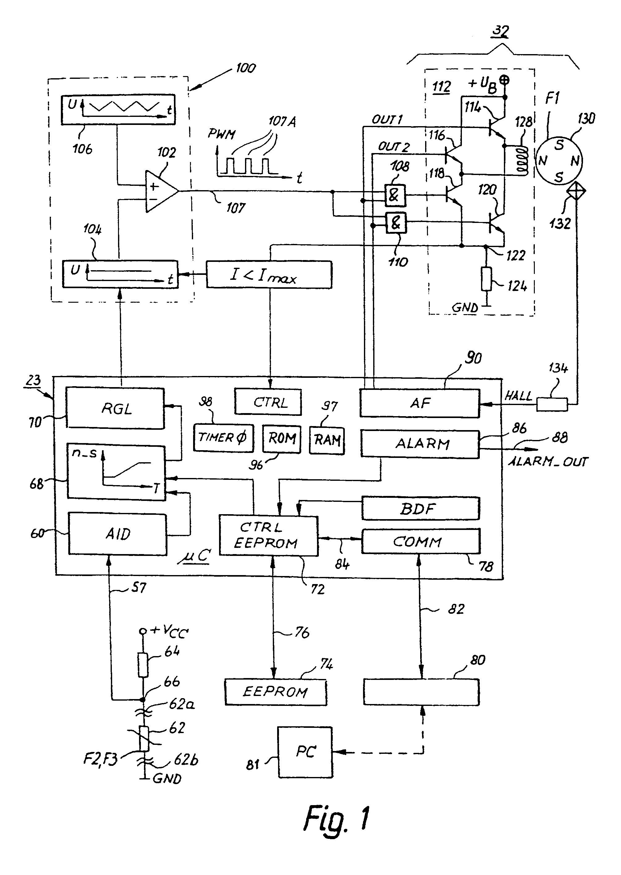
[0034]FIG. 1 shows an overview of a preferred exemplary embodiment of an electronically commutated motor (ECM) according to the present invention. The latter is controlled by means of a microcontroller (μC) 23 or alternatively a microprocessor. μC 23 comprises an A / D converter 60, a “characteristic” function 68, an RGL (controller) function 70, a “CTRL EEPROM” function 72, a “COMM” (communication) function 78, an “ALARM” function 86, and an “AF” (drive) function 90. A / D converter 60 can also be arranged outside μC 23.

[0035]An NTC (Negative Temperature Coefficient) resistor 62 is connected between a node 66 and ground (GND), and a resistor 64 is present between a voltage Vcc (e.g. +5 V) and node 66. Node 66 is connected to A / D (Analog to Digital) converter 60.

[0036]An EEPROM 74 is connected via a bus 76 to “CTRL EEPROM” function 72. Instead of EEPROM 74, a flash ROM, a reprogrammable flex-ROM cell, or another nonvolatile memory could, for example, also be used....


PUM


Abstract

If a motor becomes defective, e.g. stops running, runs too slowly, or becomes too hot, many customers demand the generation of an alarm signal, i.e. ask for an alarm device provided on the motor. The following method is used for configuring this alarm signal: At least one parameter for configuring the alarm device of the motor is inputted via a input interface (80, 82); the at least one parameter is stored in a parameter memory (74; 109); the execution of at least one routine of the alarm device provided in the microprocessor (23) is influenced by said stored parameter or by a parameter derived therefrom. The invention furthermore concerns a motor for carrying out such a method. In a motor of this kind, the alarm device can easily be configured in accordance with a customer's present needs.

Description

FIELD OF THE INVENTION[0001]The invention concerns a method for configuring the alarm device of an electric motor, and a motor for carrying out such a method.BACKGROUND[0002]EP 0 895 345 A1, corresponding to U.S. Pat. No. 5,845,045, discloses an electric motor having an alarm device (cf. FIG. 20 therein). This alarm device has little flexibility. If a customer demands changes, extensive modifications to the motor's hardware are often necessary in order to achieve them.SUMMARY OF THE INVENTION[0003]An object of the invention is to make available a method for configuring the alarm device of an electric motor, and a motor for carrying out such a method.[0004]According to the invention, this object is achieved by means of a method for configuring an alarm device of an electric motor associated with which are a microcontroller or microprocessor (hereinafter called a microprocessor), an input interface, and a parameter memory, which method comprises the following steps: via the input inte...

Claims


Application Information

Patent Timeline
IPC IPC(8): H02P6/34
CPCH02P6/001H02P6/34
Inventor HORNBERGER, JOERGJESKE, FRANKRAPPENECKER, HERMANNKALTENBRUNNER, HANSJORGKARWATH, ARNO
Owner EBM PAPST ST GEORGEN & -
Why Eureka
Try Eureka