Weatherproof electrical enclosure having an adjustable-position cover

an electrical enclosure and adjustable technology, applied in the field of enclosures, can solve the problems of the prior art enclosure, the orientation of the opening of the cover cannot be changed without remounting, and the hinges of the cover are typically pivoting

Active Publication Date: 2005-12-27
EATON INTELLIGENT POWER LTD
View PDF47 Cites 76 Cited by
  • Summary
  • Abstract
  • Description
  • Claims
  • Application Information

AI Technical Summary

Benefits of technology

[0009]The advantage of the present invention is that it makes it unnecessary to stock separate inventories of enclosures having vertically opening covers and horizontally opening covers. A further advantage of the present invention is that it allows the orientation of the cover to be changed without the need to remount or replace the entire enclosure. Another advantage of the invention is that the use of a cover plate with removable ribs makes it unnecessary to stock cover plates having different kinds of openings to match different types of electrical fixtures. Other objects, features and advantages of the present invention will become apparent when the detailed description of the preferred embodiments of the invention are considered in conjunction with the drawings which should be construed in an illustrative and not limiting sense as follows.
is that it makes it unnecessary to stock separate inventories of enclosures having vertically opening covers and horizontally opening covers. A further advantage of the present invention is that it allows the orientation of the cover to be changed without the need to remount or replace the entire enclosure. Another advantage of the invention is that the use of a cover plate with removable ribs makes it unnecessary to stock cover plates having different kinds of openings to match different types of electrical fixtures. Other objects, features and advantages of the present invention will become apparent when the detailed description of the preferred embodiments of the invention are considered in conjunction with the drawings which should be construed in an illustrative and not limiting sense as follows.

Problems solved by technology

The enclosures of the prior art, however, have a disadvantage in that their covers are typically hinged to pivot open in only one direction.
Another disadvantage of enclosures of the prior art is that once the electrical fixture is covered by or mounted within the enclosure, the direction of the opening of the cover (i.e., its “orientation”) cannot be changed without remounting or replacing the entire enclosure.
However, each of these has a problem in utilization that makes it relatively unattractive to manufacture or use.
For example, some devices incorporate complicated mechanisms that require large numbers of parts.
Other devices require the use of relatively large enclosures that occupy a large amount of space.
This makes such enclosures unsightly and impractical in situations where space is at a premium.
As such, it easy for these hinge assemblies to be accidentally detached.

Method used


Image

  • Weatherproof electrical enclosure having an adjustable-position cover
  • Weatherproof electrical enclosure having an adjustable-position cover
  • Weatherproof electrical enclosure having an adjustable-position cover

Examples


Embodiment Construction

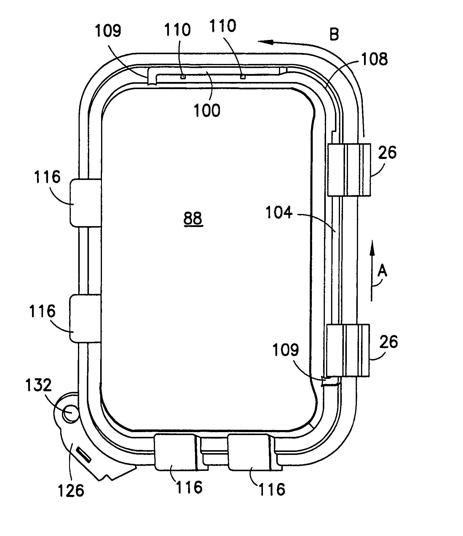
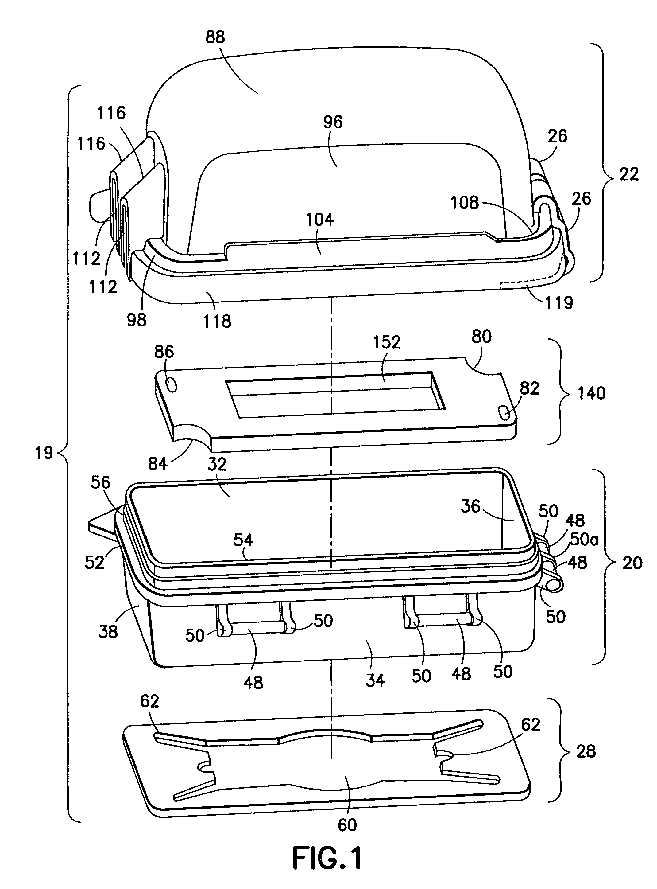
[0052]As seen in FIG. 1, an enclosure 19 in accordance with one embodiment of the present invention comprises a base 20, a cover 22, a cover plate 140, hinge clips or clips 26 and a gasket 28. The enclosure is customarily mounted in a vertical or upright position (see, FIG. 9) since electrical fixtures that would be covered by the enclosure are generally oriented vertically with respect to a support structure (e.g., a wall) to which the electrical fixture is attached. Based on the foregoing, the terms top, bottom, side, upper, lower, front, rear, left and right, as used herein with respect to the enclosure are to be understood in the context of the enclosure being in an upright or vertical position as shown in FIG. 9.

[0053]The base 20 is mountable on a support structure (not shown) generally presenting a flat surface, for example, the wall surrounding an electrical fixture. See, FIG. 9. The gasket 28 is mounted between the support structure and the base 20 while the cover plate 140 ...


PUM


Abstract

A weatherproof electrical enclosure having a base and a cover pivotably connected to the base by movable hinge clips. The position of the hinge clips can be adjusted to allow the cover to be oriented to open horizontally or vertically without needing to remove or remount the enclosure. The cover has cable openings at the top and bottom that may be shielded by hoods and may also have a latch mechanism to keep the cover in the closed position. The enclosure may also include a cover plate having ribs that can be selectively removed to create different kinds of apertures that conform to different types of electrical fixtures. The cover plate may have recesses on two diagonally opposite corners and horizontally elongated mounting holes to make it easier to install, position and remove the cover plate from the base.

Description

RELATED APPLICATION[0001]This application claims priority from U.S. Provisional Application Ser. No. 60 / 511,178 filed on Oct. 15, 2003, the disclosures of which are incorporated herein by reference.FIELD OF INVENTION[0002]This invention generally relates to enclosures for electrical fixtures such as receptacles and switches. More particularly, it relates to a weatherproof electrical enclosure having an adjustable-position cover.BACKGROUND OF INVENTION[0003]Weatherproof enclosures for protecting outdoor electrical fixtures such as receptacles and switches against the effects of the elements (e.g., rain, moisture, and dust) are well known. Typically, such enclosures comprise a generally boxed-shaped base that is sized to receive an electrical fixture, and a cover pivotably attached to the base. The enclosure may have openings for electrical cables so that the cover can be closed even when cables are attached to the electrical fixture, e.g., when an electrical plug is attached to a rec...

Claims


Application Information

Patent Timeline
Patent Type & Authority Patents(United States)
IPC IPC(8): H02G3/08H02G3/14
CPCH02G3/088H02G3/14
Inventor MARCOU, JEAN CLAUDEKNAPIK, JIMYAO, XING
Owner EATON INTELLIGENT POWER LTD
Why Eureka
Try Eureka