Test strip for measuring analyte concentration over a broad range of sample volume
What is AI technical title?
AI technical title is built by Patsnap AI team. It summarizes the technical point description of the patent document.
a test strip and sample volume technology, applied in the field of test strips, can solve the problems of difficult to bring exactly the right amount of body fluid to the test strip, test strip may not function properly, etc., and achieve the effects of minimizing any tendency for body fluid to drip, small size, and low cos
Inactive Publication Date: 2006-01-17
LIFESCAN IP HLDG LLC
View PDF69 Cites 143 Cited by
Summary
Abstract
Description
Claims
Application Information
AI Technical Summary
This helps you quickly interpret patents by identifying the three key elements:
Problems solved by technology
Method used
Benefits of technology
Benefits of technology
[0007]The invention is directed to a color-indicating test strip which operates with a relatively small volume of body fluid but is capable of absorbing and retaining several times the required volume of body fluid, thereby minimizing any tendency for the body fluid to drip from the test strip. The test strip includes a membrane containing a color-changing reagent in contact with a porous sheet that has a pillow portion adapted to absorb excess body fluid from the membrane. The membrane extends across and protrudes into a window in the test strip. The window serves both to make visible any color change and to allow oxygen access to the membrane. The pillow portion is located in a protective channel defined by a relatively rigid container. The test strip is small, inexpensive, and suitable for mass production by heat-sealable packaging methods.
Problems solved by technology
It is sometimes difficult to bring exactly the right amount of body fluid to the test strip.
If too little fluid is delivered, the test strip may not function properly.
If too much fluid is applied to the test strip, excess fluid may drip from the test strip.
Method used
Image
Click on the blue label to locate the original text in one second.
Reading with bidirectional positioning of images and text.
Examples
Embodiment Construction
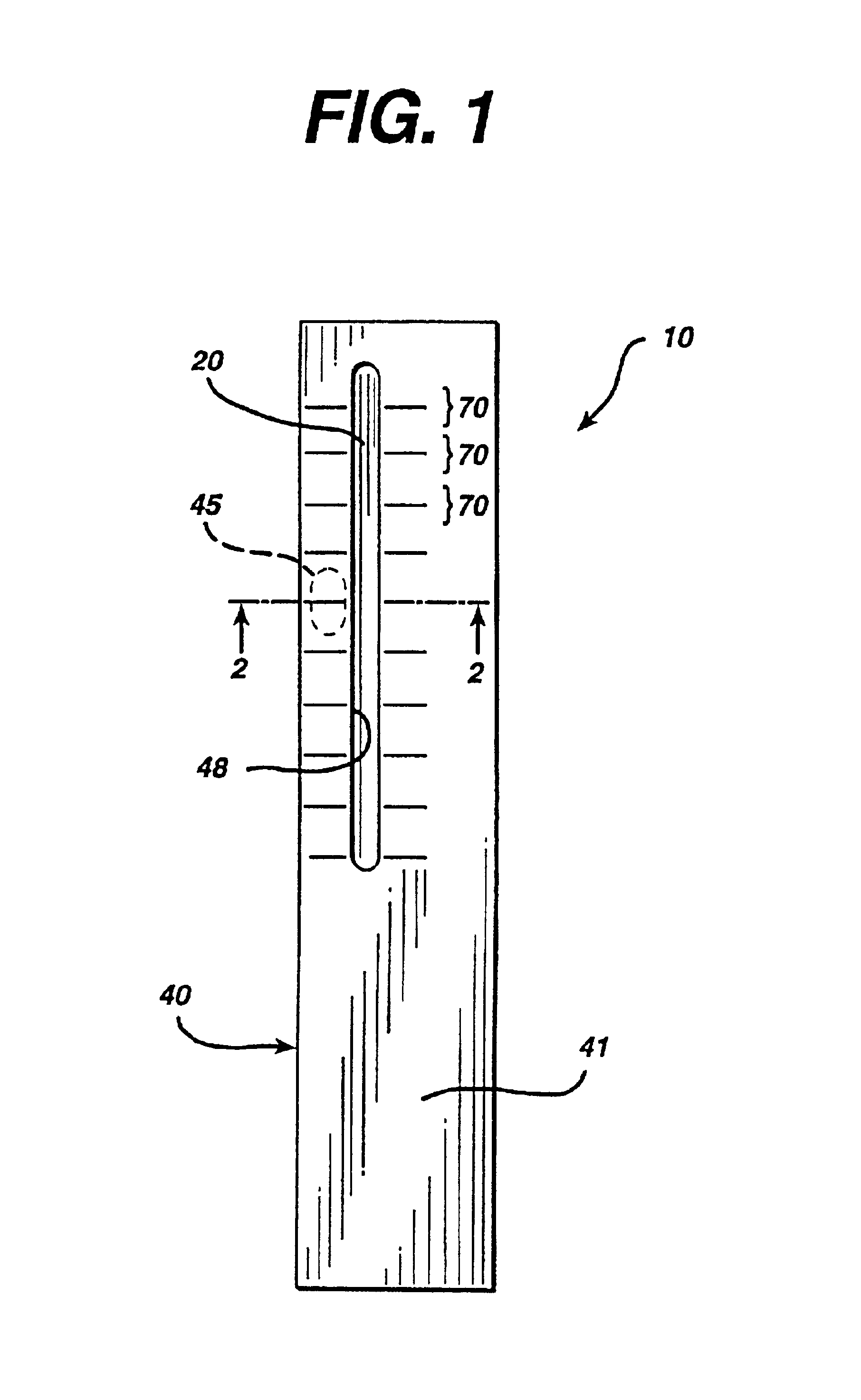
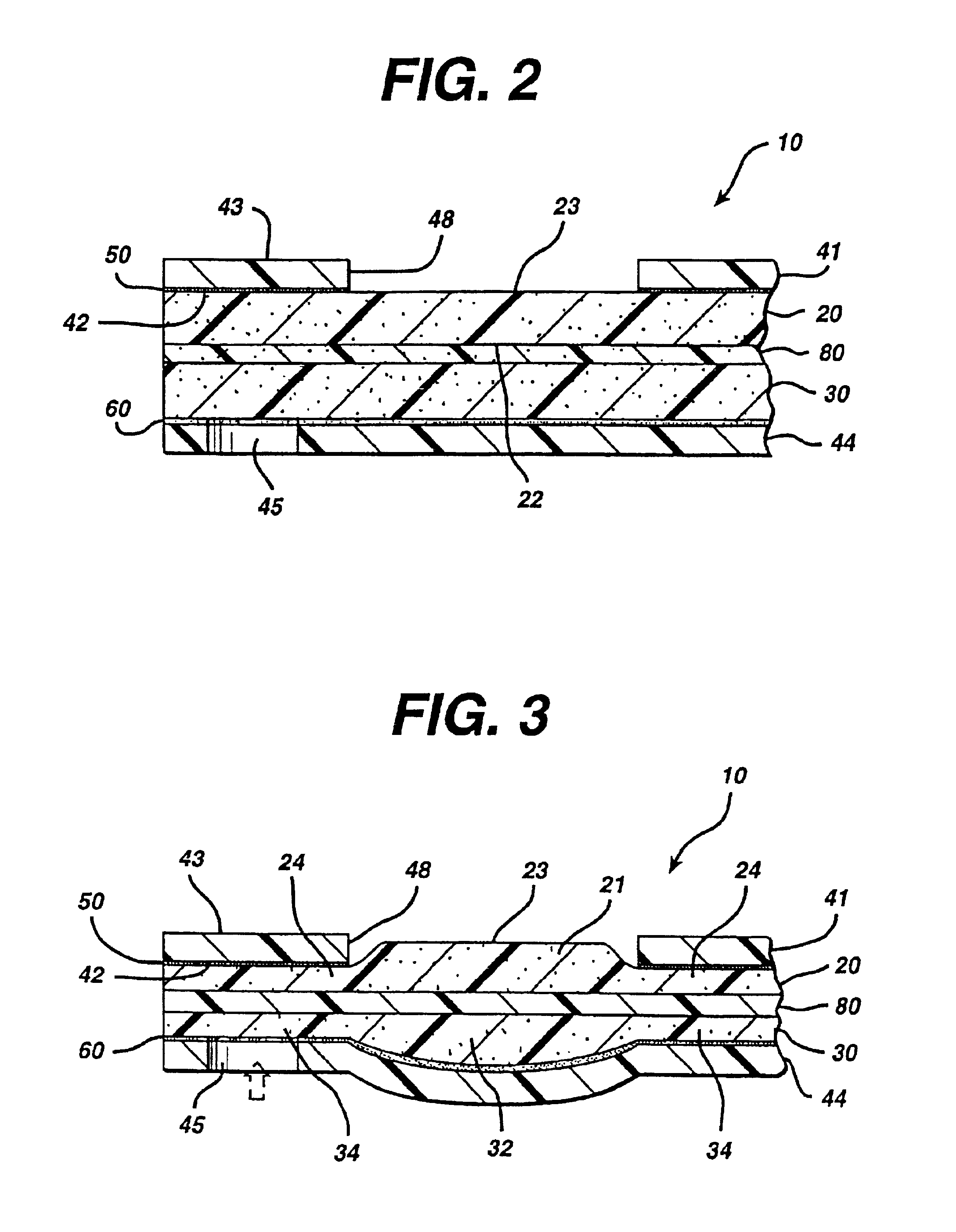
[0023]A test strip in accordance with the present invention is illustrated in FIG. 1. FIGS. 2 and 3 depict a cross section through the strip of FIG. 1 before and after the strip is compressed, respectively. The test strip 10 comprises a porous membrane 20 having a sample side 22 and a testing side 23, as can be seen in FIGS. 2 and 3. A testing reagent is held within the pores of the membrane. A portion of the membrane is adapted to absorb a body fluid, such as blood, which comes in contact, with the sample side 22. The membrane transports the body fluid by capillary action from the sample side 22 toward the testing side 23, where the testing reagent reacts with the analyte to produce a color change. The change in color depends on the concentration of analyte in the sample and enables one to determine the concentration.
[0024]Depending on the composition of the testing reagent, the strip can be used to measure analytes such as glucose, cholesterol, proteins, ketones, uric acid, phenyl...
PUM
Property
Measurement
Unit
thickness
aaaaa
aaaaa
thickness
aaaaa
aaaaa
diameters
aaaaa
aaaaa
Abstract
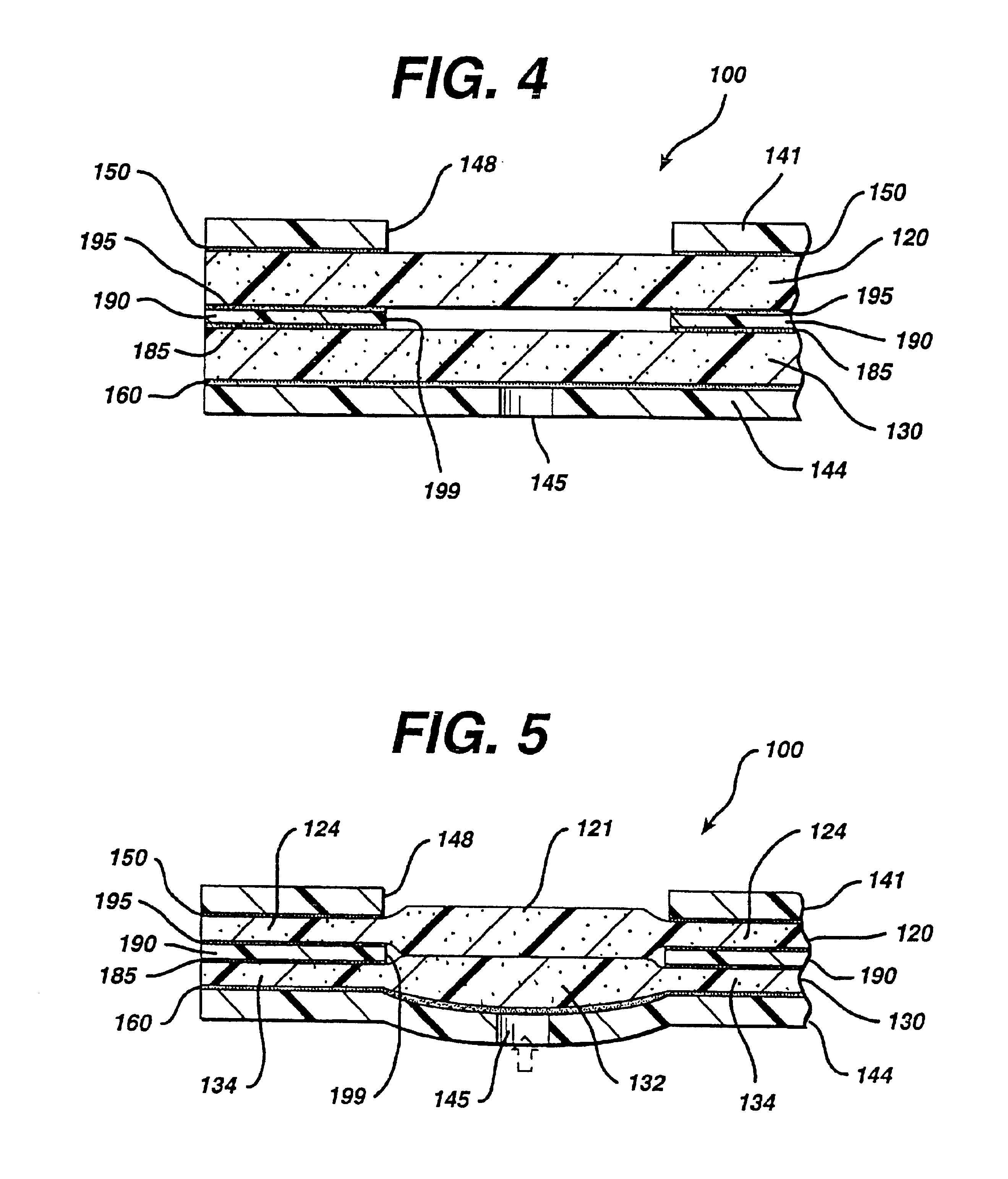
A test strip for determining the concentration of an analyte in a body fluid includes a membrane in fluid communication with a porous layer. The membrane and the porous layer are divided into compressed portions, which restrict the capillary flow of the body fluid, and uncompressed portions. The uncompressed portions are adapted to absorb and retain body fluids in excess of the amount required for operation of the test strip. The test strip may be constructed with an internal relief chamber to accommodate the uncompressed portions. A method of making the test strip by pressure and / or heat sealing individual components on a shaping die is also provided.
Description
CROSS-REFERENCE TO RELATED APPLICATIONS[0001]This application is a divisional of U.S. patent application Ser. No. 08 / 442,035, filed May 16, 1995, now U.S. Pat. No. 6,395,220, which is a continuation-in-part of U.S. patent application Ser. No. 07 / 960,579, filed Oct. 13, 1992, now U.S. Pat. No. 5,418,142, which is a continuation of U.S. patent application Ser. No. 07 / 691,192, filed Apr. 25, 1991, abandoned, which is a continuation of U.S. patent application Ser. No. 07 / 399,055, filed Aug. 28, 1989, abandoned, and is a continuation-in-part of U.S. application Ser. No. 07 / 736,537, filed Jul. 26, 1991 now U.S. Pat. No. 5,306,623.BACKGROUND OF THE INVENTION[0002]1. Field of the Invention[0003]The present invention relates to a test strip which allows a user to determine the concentration of an analyte in a liquid test sample. The test strip includes an absorbent membrane and a reagent that undergoes a change in color when exposed to the analyte, such as glucose or cholesterol, in a body f...
Claims
Application Information
Patent Timeline
Application Date:The date an application was filed.
Publication Date:The date a patent or application was officially published.
First Publication Date:The earliest publication date of a patent with the same application number.
Issue Date:Publication date of the patent grant document.
PCT Entry Date:The Entry date of PCT National Phase.
Estimated Expiry Date:The statutory expiry date of a patent right according to the Patent Law, and it is the longest term of protection that the patent right can achieve without the termination of the patent right due to other reasons(Term extension factor has been taken into account ).
Invalid Date:Actual expiry date is based on effective date or publication date of legal transaction data of invalid patent.

